Continue to Site

Welcome to EDAboard.com

Welcome to our site! EDAboard.com is an international Electronics Discussion Forum focused on EDA software, circuits, schematics, books, theory, papers, asic, pld, 8051, DSP, Network, RF, Analog Design, PCB, Service Manuals... and a whole lot more! To participate you need to register. Registration is free. Click here to register now.

[SOLVED] Hopefully simple voltage regulation question

Status
Not open for further replies.

dxpwny

Advanced Member level 4
Joined
Jun 29, 2008
Messages
111
Helped
2
Reputation
4
Reaction score
2
Trophy points
1,298
Activity points
2,473
I have a small sealed device that has a USB interface and runs off an internal rechargable battery when not connected to a USB port.

I'd like to add an external 9V battery to extend it's life before a recharge is needed. I attached a 9 V battery to a 78L05, and then the 5 V output to the USB conneector. Made it run nearly twice as long (it uses only about 27 mA).

Only afterwards did I take the time to find out that the device will run with as little as 3.8 V applied. So, by using the 78L05, I was 'wasting' some of the batteries power - the 78L05 would 'shut off' once the battery voltage dropped below about 5V.

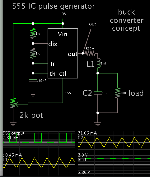
So, I'm wondering what would be the most efficient method of attaching a common 9V battery to the USB connector and allow the device to be able to run as long as possible.

I thought of connecting the 9V battery to a LM317 set to output about 3.8V. To make things as efficient as possible, I'd have to make the adjustment resistors a high value to lessen the 'wasted' current ... right ?

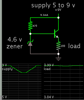
Also thought of just using a resistor / zener diode with voltage as close to 3.8 V as I can find. In that case I'd want to use a low value resistor to keep its voltage drop as low as possible ... right ?

Which approach would likely be more efficient ... or is there another possibility I am not seeing ?
 

Any reason you can't operate on 3.3V? If your device does not need 5V when it is not connected to the USB port, I would suggest you redesign your system for 3.3V operation if possible and use a Li-Polymer or ion battery (possibly with a low dropout regulator) as a power source. Btw, why can't it go lower than 3.8V? Plus, there are also a lot of integrated solutions for USB + Li battery power management and charging:

One example from TI: https://www.ti.com/product/bq24040

I think using a 9V battery is not the best way to go if you really want to maximize efficiency since you will be wasting a lot of energy to drop 9V down to 5 or 3.8 volts. Of course, it all comes down to what your other design requirements/constraints are (i.e. budget, complexity, access to/availability of components).
 

The device is sealed. It requires a minimum of 3.8 V.
 

Then maybe a switching regulator is best for you (in terms of efficiency) to get 3.8V from a 9V battery and not a linear voltage regulator if you don't mind the increased complexity.
 

OK ... will research that - thanks
 

This simple buck converter may suit your purpose. Or, from another standpoint, the inductor acts as a choke input filter for pulses from the 555 timer IC.

It's untested. Experimentation will be needed.


You adjust the output voltage via the potentiometer. This changes the voltage applied to the 'ctrl' pin on the 555, changing the duty cycle.

The 555 output can source and sink current. The limit is 200mA. My design stays under that limit.
 

Trying to go with simplicity. I have no low voltage zeners, so am trying to do something with a lm317. Pretty sure I have the pin-out right, but things don't seem to be working. The output varies significantly with the input.

In other words I can set the input to 5 V, then adjust the pot so I get 3.8 out. Then increase the input a volt, and the output jumps too much.

What might I be doing wrong ?
 

This simple buck converter may suit your purpose. Or, from another standpoint, the inductor acts as a choke input filter for pulses from the 555 timer IC.

It's untested. Experimentation will be needed.


................
That circuit is unregulated so its output voltage will drop as the battery voltage drops.
Any circuit for this purpose needs to have a regulated output.

- - - Updated - - -

Trying to go with simplicity. I have no low voltage zeners, so am trying to do something with a lm317. Pretty sure I have the pin-out right, but things don't seem to be working. The output varies significantly with the input.

In other words I can set the input to 5 V, then adjust the pot so I get 3.8 out. Then increase the input a volt, and the output jumps too much.

What might I be doing wrong ?
The LM317 needs an input voltage at least 2V above the output voltage to properly regulate, so the minimum input voltage should be greater than 6V for a 3.8V output.
To regulate from 5V you would need a low-dropout type regulator.
 

Oh well, there is still the old standby:


The supply V was dropped from 9 to 5V and back. Load voltage changed very little.

A 4.6V zener can be assembled from a few diodes. You can raise the zener voltage a bit by adding a few ohms inline.

It may also be useful to put resistance in the bias wire.
 

This is efficient linear regulator. The diode lifts up the output from 3.3V to 3.8V. You can use any low power LDO 3 pins 3.3V regulator.
 

I did some digging in my stock room ... found I have some LT1086 (3.3 V fixed) and 75901, MIC29372 and MIC29201 (all 3 are adjustable) .... all four are LDO regulators. Will try the above diode/LM2936 example.
 

The diode will indeed raise the voltage but has a temperature coefficient of about -2mV/°C, which will cause a similar change in the regulated output voltage.
You'll have to decide if that's acceptable in your application.
 

Status
Not open for further replies.

Similar threads

Part and Inventory Search

Welcome to EDABoard.com

Sponsor

Back
Top