Mohammad Zubair
Junior Member level 3

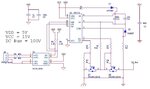
I am using this circuit. As DC bus I am applying currently 30V and at output I am able to achieve a sine wave by further employing a filter Circuit
In theory what should be the peak output voltage of the sine wave???? Shouldn't it be +30V
I am getting a peak of +12.5V and 25V p-p.