Continue to Site

Welcome to EDAboard.com

Welcome to our site! EDAboard.com is an international Electronics Discussion Forum focused on EDA software, circuits, schematics, books, theory, papers, asic, pld, 8051, DSP, Network, RF, Analog Design, PCB, Service Manuals... and a whole lot more! To participate you need to register. Registration is free. Click here to register now.

analog ramp vhdl code vhdl

Status
Not open for further replies.

jimmykk

Full Member level 3
Joined
Oct 2, 2014
Messages
158
Helped
0
Reputation
0
Reaction score
1
Trophy points
1,298
Activity points
2,863
hi
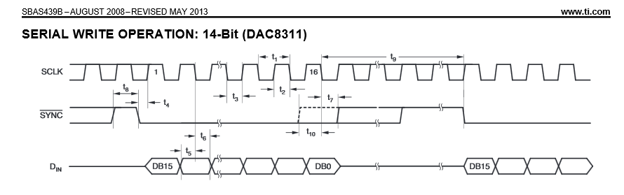
I was trying to make a ramp voltage using spi dac8311 which will be interfaced with the altera de1 soc board through GPIO bus. thee clock needs to be divided down to 5 mhz for DAC OPERATION and ramp voltagE should be between 0 and 3 V.
In my code down, i wan to increase the value by 3 every time the register is updated and then pass this value serially. But i am not getting my desired result, can anybody help me in where i am doing wrong.


Code VHDL - [expand]
1
2
3
4
5
6
7
8
9
10
11
12
13
14
15
16
17
18
19
20
21
22
23
24
25
26
27
28
29
30
31
32
33
34
35
36
37
38
39
40
41
42
43
44
45
46
47
48
49
50
51
52
53
54
55
56
57
58
59
60
61
62
63
64
65
66
67
68
69
70
71
72
73
74
75
76
77
78
79
80
81
82
83
84
85
86
87
88
89
90
91
92
93
94
95
96
97
98
99
100
101
102
103
104
105
106
107
108
109
110
111
112
113
114
115
116
117
118
119
120
121
122
123
124
125
126
127
128
129
130
131
132
133
134
135
136
137
138
139
140
141
142
143
144
145
146
147
148
149
150
151
152
153
154
155
156
157
158
159
160
161
162
163
164
165
166
167
168
169
170
171
172
173
174
175
176
177
178
179
180
181
182
183
184
185
186
187
188
189
190
191
192
193
194
195
196
197
198
199
200
201
202
203
204
205
206
207
208
209
210
211
212
213
LIBRARY IEEE;
use ieee.std_logic_1164.all;
use ieee.std_logic_unsigned.all;
 
 
entity dac is
port(
clock_50 : in std_logic;
GPIO_1   : inout std_logic_vector(35 downto 0)
);
end dac;
 
architecture arch of dac is
 
type state_type is (init, receiving, sending_1, sending_2, sending_3, sending_4, sending_5,
                    sending_6, sending_7, sending_8, sending_9, sending_10, sending_11, 
                          sending_12, sending_13 , sending_14 ,sending_15 ,sending_16 ,sending_17,
                    sending_18);
                          
signal present_state : state_type := init;
signal data_i          : std_logic_vector(13 downto 0) := "00000000000011";
signal clk             : std_logic;
signal memory_i        : std_logic_vector(13 downto 0);                   
 
signal count : integer range 0 to 9;
begin 
GPIO_1(1) <= clk;
process(clock_50)
 
begin
 
if (rising_edge(clock_50)) then
 if (count = 9) then          -- divide 50 Mhz BY 10 TO GET A 5Mhz clock
 count <= 0;
 clk   <= not clk;
 else 
 count <= count + 1;
 end if;
end if;
end process;


process(clock_50)
 
variable int_cnt       : integer range 0 to 81;
variable sample_count  : integer range 0 to 5001; -- loop for generation of increasing control voltage for amplifier 
 
begin
 
if (rising_edge(clock_50)) then
if (count = 9 and clk ='1') then
case present_state is 
 
when init=>
sample_count := 0;
GPIO_1(0)         <= '1';
GPIO_1(2)         <= '0'; 
memory_i     <= (others => '0');
present_state <= receiving;


when receiving =>
GPIO_1(0)         <=  '1';
int_cnt      :=   0;
GPIO_1(2)         <= '0';
--memory_i <= to_unsigned(i,14);
memory_i <= memory_i + data_i;
--memory_i     <=  memory_i+ to_unsigned(i,14);
 
 
if(sample_count<4900) then
present_state <=sending_1;
else
present_state <= init;
end if;


when sending_1 => 
GPIO_1(0)            <= '0';
GPIO_1(2)            <= '0';
present_state   <= sending_2;
 
when sending_2 =>
GPIO_1(0)            <= '0';
GPIO_1(2)            <= '0';
present_state   <= sending_3;
 
when sending_3 =>
GPIO_1(0)            <= '0';
GPIO_1(2)            <= memory_i(13);
present_state   <= sending_4;
 
when sending_4 =>
 
GPIO_1(0)            <= '0';
GPIO_1(2)            <= memory_i(12);
present_state   <= sending_5;
 
when sending_5 =>
 
GPIO_1(0)            <= '0';
GPIO_1(2)            <= memory_i(11);
present_state   <= sending_6;
 
when sending_6 =>
 
GPIO_1(0)            <= '0';
GPIO_1(2)            <= memory_i(10);
present_state   <= sending_7;
 
when sending_7 =>
 
GPIO_1(0)            <= '0';
GPIO_1(2)            <= memory_i(9);
present_state   <= sending_8;
 
when sending_8 =>
 
GPIO_1(0)            <= '0';
GPIO_1(2)            <= memory_i(8);
present_state   <= sending_9;
 
when sending_9 =>
 
GPIO_1(0)            <= '0';
GPIO_1(2)            <= memory_i(7);
present_state   <= sending_10;
 
when sending_10 =>
 
GPIO_1(0)            <= '0';
GPIO_1(2)            <= memory_i(6);
present_state   <= sending_11;
 
when sending_11 =>
 
GPIO_1(0)            <= '0';
GPIO_1(2)            <= memory_i(5);
present_state   <= sending_12;
 
when sending_12 =>
 
GPIO_1(0)            <= '0';
GPIO_1(2)            <= memory_i(4);
present_state   <= sending_13;
 
when sending_13 => 
 
GPIO_1(0)            <= '0';
GPIO_1(2)            <= memory_i(3);
present_state   <= sending_14;
 
when sending_14 =>
 
GPIO_1(0)            <= '0';
GPIO_1(2)            <= memory_i(2);
present_state   <= sending_15;
 
when sending_15 =>
 
GPIO_1(0)            <= '0';
GPIO_1(2)            <= memory_i(1);
present_state   <= sending_16;
 
when sending_16 =>
 
GPIO_1(0)            <= '0';
GPIO_1(2)            <= memory_i(0);
present_state   <= sending_17;
 
when sending_17 =>
 
GPIO_1(0)            <= '1';
GPIO_1(2)            <=  '0';
present_state   <= sending_18;


when sending_18 =>
 
int_cnt  := int_cnt + 1;
GPIO_1(0)     <= '1';
GPIO_1(2)     <= '0';
 
if (int_cnt = 80) then
sample_count  := sample_count + 1;
present_state <= receiving;
else 
present_state <= sending_18;
end if;


when others =>
GPIO_1(0)            <=  '1';
present_state   <=  sending_18;
 
end case;
end if;
end if;
end process;
 
 
end architecture;

 
Last edited by a moderator:

I ran a simulation, other than a missing := '0' on the signal definition of clk (without it the simulation outputs U's). I can't determine what you are seeing that isn't right. The simulation outputs a serial stream of the contents of memory_i.
e.g.
Capture.JPG

Though I wouldn't code it like you have, with each bit having it's own state.

I would add a shift register that holds the last updated value of memory and shift that out serially in a single state called something like shift_data and use a counter to determine how long to stay in that state. Doing it the way you are requires a large multiplexer to output each bit based on the state variable (the select on the multiplexer).
 

Yes, your serial output bits (gpio[2]) are changing on the falling edge (gpio[1]), when they should have been changed on the rising edge. That would certainly explain why you can't get the DAC to work.

I gather you didn't run a simulation on your code before posting, as you noticed this was a problem in the simulation waveform I posted. As it should be readily apparent now, simulation is your best friend when designing with VHDL/Verilog, so run simulations next time. :)
 
Status
Not open for further replies.

Similar threads

Part and Inventory Search

Welcome to EDABoard.com

Sponsor

Back
Top