Continue to Site
Follow along with the video below to see how to install our site as a web app on your home screen.
Note: This feature may not be available in some browsers.
No idea what exactly mean with "key clicks" in this regard. Is it contact bouncing? If so, it's an unavoidable effect of mechanical relays.
If you are just annoyed about relay sounds, use a different relays or mount it differently.
The best solution is not to use a relay, but to perform low voltage electronical keaying of the oscillator.
What I mean is that, if you see the spectrum of the transmitter that is keyed (tx signal dounconverted to audio, using a receiver) in the waterfall display of an fft program, you are going to notice little glitches where the beginning ang the end of the keyed signal parts (TX on). http://www.dxatlas.com/Rocky/KillClickOFF.JPG
They happen because of the rapid switching of the relay contacts or is an electronic switch is switched rapidly.
If a relay is used, I think a shunt capacitor from the relay output to the GND will reduce the ending clicks, but I am not sure about the click at the beginning of the signal.
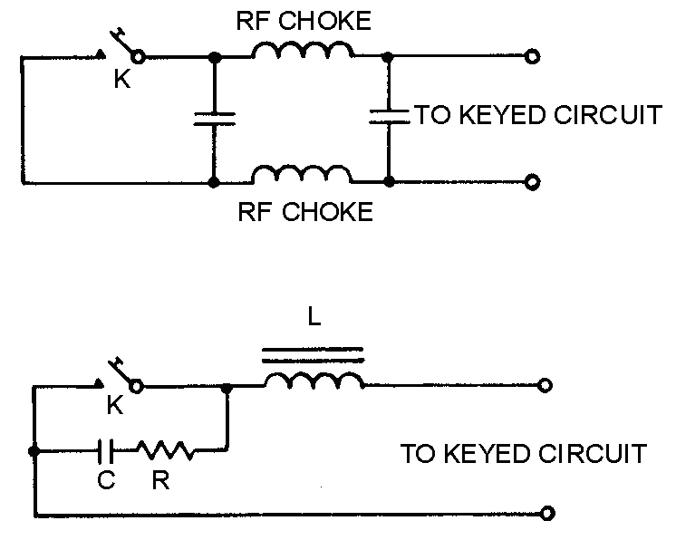
I believe the first post is rather misleading. You are talking about switching transients in transmitter spectrum which are an unavoidable supplement of OOK (on-off keying) modulation. You can reduce it by ramping the PA output over several millisecónds. The suggested low-pass filters may work for it, if dimensioned suitably.
The first circuit will not affect the key clicks. The second would if placed directly on the electronic end of the keyer. i.e. if the TX is keyed by grid blocking then the circuit must be connected directly to it, not to the relay coil, but to its contacts.
I would think if the time constant of the R and C, should be 1mS. Adding the L improves its performance but at a great cost.
If you show how the TX is keyed perhaps we could suggest something.
Frank
No, no, no, its the not RF bit, we have seen the relay energising circuit before. Does it switch the Vcc on an RF amp, block a stage with a cut off bias or what?
Frank
So if the Vcc is reduced on your class A amplifiers, you get the clicks. Have you tried opening the emitter lead?, switching in a lot of base current (series collector resistor required) to saturate the transistor? Replacing a series feed capacitor with two putting a diode at the intersection to earth and switching the diode on to short out the RF path (several diodes in series may be required, depending on RF level).
Frank
If your 100mW is unstable when Vcc is reduced, then that must be fixed, then transistor with one shot on key pulse can be used.
When fixed then to use 1st order LPF at 300 Hz or a time decay dv/dt of 1.5ms then Ic=Cdv/dt so choose C = Ic/1.5ms or so.
For improved spectral stop band, 2nd or 3rd order LC LPF filter with Q~1 based on impedance of LC at 300Hz and effective load impedance of 100mW Tx.
How can the output RF output signal be undistorted when VCC is instantaneously reduced?
You don't switch instantaneous because of supply time constants (capacitors) so the PA will go through "bad" operating points with heavy distortion. And even if you could switch instantaneous, you don't switch at zero crossing of the RF, so that causes some (smaller) distortion.
I think switching the supply of the PA is about the worst place for keying.Why don't you key at smaller RF levels ealier in the TX chain? There are all sorts of RF switches.
You mention that there are all sorts of RF switches for low powers. What do you mean by that, a simple relay?
")
The CW wave shaping theory (with examples) I think is presented in all ARRL handbooks back to 1930'ties. And when I said all handbooks, I mean all of them.
go to page 14.50
http://mxh.strefa.pl/pliki/tech/book2006/14.pdf
The main rule is that never ever switch a high current or a high voltage stage.
The top-end transceivers switch the CW transmitter signal in more stages. They switch the DC bias of buffer stages, and sometime switch simultaneous the TX IF signal path.
All these switching use a careful timing, providing at the end a nice shape of the CW signal.