Continue to Site

Welcome to EDAboard.com

Welcome to our site! EDAboard.com is an international Electronics Discussion Forum focused on EDA software, circuits, schematics, books, theory, papers, asic, pld, 8051, DSP, Network, RF, Analog Design, PCB, Service Manuals... and a whole lot more! To participate you need to register. Registration is free. Click here to register now.

[SOLVED] Conditioning circuit for microphone

Status
Not open for further replies.

electroman2000

Member level 2
Joined
Feb 3, 2015
Messages
44
Helped
1
Reputation
2
Reaction score
1
Trophy points
8
Activity points
496
Hi everyone,
I'm developing a system that store the voice recorded by a microphone into a SD card trough a microcontroller. I would ask a question about the conditioning circuit for the microphone. I set the voltage reference of microcontroller's ADC at 3.3 V and 0 V for high and low voltage reference respectively. The microhpone is a preamplified condenser microphone; in the datasheet is reported that the max output voltage is 0.355 V rms.
I want design a conditioning circuit that can match perfectly microhpone output with ADC's microcontroller input and, of course, translate all negative voltages in positive voltages. I made the following calculation, tell me if I'm wrong:
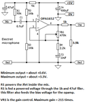
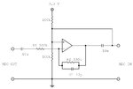
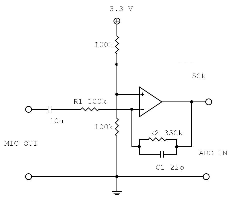
I first calculated the max output voltage: 0.355*sqrt(2) = 0.5 V. Then I suppose a max positive voltage of 0.5 V and a max negative voltage of -0.5 V (I'm not sure of this). To have only a positive voltage in ADC input, I must design a "mute voltage" of 3.3/2=1.65 V. Then, the max variation I can have without damage the ADC and using all range is 1.65. So I calculated the max gain, that is 1.65/0.5= 3.3. I attach the circuit that I have made: a low pass filter with a single supply voltage. The two 100K resistor split the voltage for the single supply AND provide the "mute voltage" at the input of ADC. The R2=330kohm and C2=22pF provide a cutoff frequency of about 22 kHz. R1=100khom provide a gain of 330k/100k=3.3.

Will I reach the max matching between microphone and ADC with this circuit?

Thank you everyone and sorry for my english.
 

Attachments

  • cond_mic.jpg
    cond_mic.jpg
    40.6 KB · Views: 123

It will probably oscillate....
The output is never connected to positive input directly otherwise phase will be 0 degree and feedback loop gain will be more than one and it will start to sing...
 

I simulated it with Pspice. Indeed it oscillates. I don't understand why, even your explanation. Btw it clearly show the benning of oscillation; it oscillates at 500 Hz and has a min value of 0.5 V and max value of 2.65 V using a 5 Khz 0.5 V amplitude input sine wave.
I tryied to put a resistor of 50 Khom between the positive input of OP AMP and voltage divider, but nothing happeans.
I used this document as reference for single supply OP AMP

Explanation is very simple...
If any system has a Closed Loop gain >1 and Closed Loop Phase=0 it will absolutely oscillate.

Can you tell me what your exact intention is ?? You would put a threshold for incoming signal ???
 

Ahhhh ok now I understand.
I tought I had explained my intentions in the OP. I try to explain better what I would do. I have a microphone that have a max output voltage of 0.355 V rms. I want filter the output upto 22 khz. For a better use of voltage range, I also would amplify this signal, of course under the max value supported by the microcontroller, 3.3 V.
Now, because the ADC doesn't take the negative value, I Want to add a costant value, Vcc/2, so the audio will produce a voltage variation ranging from 0 (min) to Vcc (max) and the voltage of silence is Vcc/2.
So the circuite that I have posted is a filter plus a gain. I found it in the link that I have posted.

It's so simple...
Place a pull-up resistor that connected to VDD/2 at the input of the ADC and drive this ADC through a proper high valued capacitor so signal swing will be around VDD+- output signal swing at OPAMP circuit.
Design a Audio OPAMP circuit that will have a gain around 5-7 with a filter as you desired..that's it..
 
The max voltage of the mic is in RMS ?

I would have thought it would be expressed as Vp [peak voltage].
 

It's so simple...
Place a pull-up resistor that connected to VDD/2 at the input of the ADC and drive this ADC through a proper high valued capacitor so signal swing will be around VDD+- output signal swing at OPAMP circuit.
Design a Audio OPAMP circuit that will have a gain around 5-7 with a filter as you desired..that's it..
with pull up resistor it works but not as expected. First, the wave isn't exactly a sine wave, but is a truncated sine wave (simil square wave at the peak). Second, the max peak is 2.8 V instead 3.3 V and the min peak is 0.28 V instead of 0, so the mean value is 1.26 instead of 1.65 V.
Look at the attached image to see how I have configured the pull up resistor

The max voltage of the mic is in RMS ?

I would have thought it would be expressed as Vp [peak voltage].
yes, as I said in the data sheet the max output voltage of the mic is expressed in RMS, and it is 0.355 V rms. I calculated the peak voltage multiping this value for sqrt(2), obtaining 0.5 V peak.

cond_mic.jpg

EDIT: I solved the problem. I supply the OP AMP with 5 V, and then use another voltage divider to provide the Vcc/2 at the input of ADC. ; maybe the problem was the saturation of OP AMP, wich was working with input signal near the voltage supply. Now I have an output signal ranging from 30 mV to 3.1 V, with a mean voltage of 1.55 V. I don't know why the upper 0.2 V are lost. But anyway is a good result for me.
 
Last edited:

Do you actually need the output high-pass in your application? Otherwise this simplified circuit achieves same output bias.


No I don't need it, I put a capacitor on output only for deleting an eventual continuos voltage. But maybe it is conceptually wrong.
EDIT: I simulated your circuit. It has an average voltage of 1.25 V (max output 2.9 V, min 0.4 V
 

It has an average voltage of 1.25 V (max output 2.9 V, min 0.4 V
The calculation doesn't fit. Average for a symmetrical input voltage is 1.65V, which is also the expectable output bias without input signal (and for any input signal below output clipping).
 

So? How can I investigate the reason of this strange result? For the simulation I used Pspice, OP AMP uA471, 5 kHz 0.5 V input sin wave.
 

For the simulation I used Pspice, OP AMP uA471, 5 kHz 0.5 V input sin wave.
That's, excuse me, ridiculous. 741 would never work with 3.3 V supply and has huge saturation voltage for both positive- and negative-going output.

It was definitely a fault not to ask before which OP is used in your circuit.

Maybe you observe simple input to output feedforward without any amplification, or just an unrealistic OP model. Repeat with a state-of-the-art 3.3V capable rail-to-rail amplifier, e.g. TLV2371.
 
Thank you very much. It was my fault not to consider the specification of OP AMP. I will try a real circuit with TL082. And next time I will consider the specification even in the simulation.
Thank you again
 

Indeed I just see this in datasheet :( I will try with TLV2371 that you have suggested. Thanks!
 

I think you have an ordinary electret mic. It is a condenser mic with a Jfet inside to convert its extremely high impedance down to a lower usable impedance. The Jfet is not a preamp. Its absolute maximum output is 0.355V in a rock concert or hurricane!!
I have designed and used preamps for electret mics for many years.

If the mic is 10cm from your mouth and you are speaking in a normal conversation level then the output from the mic into a resistance of 33k or more is 10mV which is only 0.01V. If you scream very loudly then its output might be 333mV.

But do you have very loud sounds? For a person speaking normally into a mic at a 10cm distance then I set the preamp gain at 50 times for an output level of 0.5V. If the mic must pickup a conversation amongst a few people and is at a distance of 2m then the preamp gain is 200 times. The gain of your preamp is only 3.3 times.
I made a sound level meter for my family room that shows levels from a whisper in the next room to the hi-fi playing loud music or TV. The gain of its electret mic is 1820 times for low sound levels then when the range of sound levels exceed 30dB the gain is automatically reduced 20dB to 182 times. Then the total range of sound levels it can show is 50dB.

Since the gain of a mic preamp must be so high and the input resistance must be 33k or more then your inverting opamp circuit would not work because its input resistance would be so low that it would seriously load down the output from the mic to almost nothing. Use a non-inverting opamp amplifier instead.

The lousy old 741 general purpose opamp was designed 47 years ago to use only a 30V supply for DC and low frequency circuits. Its datasheet shows that with a high resistance load then some of them will have no output voltage swing when the supply is 8V or less. I tried one in an audio project 40 years ago and it was awful I so never used one again. It is much too noisy (hiss) to be used for audio. I have used TL071 single, TL072 dual and TL074 quad audio low noise opamps for most of my long career in audio but there are many newer better ones available today.

The TLV2371 rail-to-rail opamp has 5 times as much noise as an audio opamp. For a frequency response up to 20kHz its gain must be limited to 100 times.
 
very usefull comment Audioguru, many thanks. I'm a newbie about analog design, because my education focused on digital design and microelettronics. It's ever a pleasure to receive suggestion from experts. The fact that the max output is reached only with very loud sounds is logic, but I didn't think at it. For my application I would register normail speaking person at about 10-15 cm distance from microphone. So, if I well understand your suggestion, I should use a gain of about 150 (because, if you in this condition set the gain to 50 and obtain a 0.5 V, I want to obtain about 1.65 so I need to multiply for about 3). It's right?
Instead I don't understand very well the implication of resistor value.
Btw I think I need to use a zener diode to avoid voltage above 3.3 V on ADC pin of microcontroller, if someone screams into the mic.
For the audio low noise op amp, I found this: OPA1652. It seems good for my application.
 

Sounds have varying levels. The average output of a mic with speech at a distance of 10cm is 10mV. Its peak levels will be at be at 33mV to about 100mV.
Sound has AC signals that swing positive and negative if the opamp has a dual-polarity supply or the level swings close to 0V then swings near the positive supply if the opamp has a single positive supply.
The levels are measured in RMS volts. But the ADC uses peak-to-peak volts. The maximum input for your ADC is a little below 0V to a little above its positive supply voltage of 3.3V.

The maximum gain of the preamp is set so that the lowest mumbling person can still be recorded loud enough to hear but then the gain is too high for normal speech level and is much too high for someone who speaks loudly or who "eats the mic" (too close). Then you adjust the maximum undistorted output level with gain control potentiometer.

The OPA1652 is a good audio opamp but its output is not rail-to-rail, it has output voltage loss and its minimum single positive power supply voltage is 4.5V. Maybe you should use a +5V supply, then the maximum output of the opamp will be about +0.8V to +4.2V which is too high for your ADC. A zener diode will short circuit the output of the opamp which is bad.

Simply attenuate the output from the opamp with two series resistors so the maximum output is from +0.6V to +3.3V.

I designed a custom preamp circuit for you:
 

Attachments

  • custom mic preamp1.png
    custom mic preamp1.png
    12.7 KB · Views: 109
What is the porpouse of the final 3.9k resistor?
Since the ADC of my microcontroller require a low input resistance for keeping low the sampling time, can I put a buffer between the output of your circuit and my ADC? or in this circuit the output resistence is already low enough?
A 0.6 V start voltage mean that I lose about 20% of entire swing of ADC...not a bad thing?
 

Status
Not open for further replies.

Similar threads

Part and Inventory Search

Welcome to EDABoard.com

Sponsor

Back
Top