Continue to Site

Welcome to EDAboard.com

Welcome to our site! EDAboard.com is an international Electronics Discussion Forum focused on EDA software, circuits, schematics, books, theory, papers, asic, pld, 8051, DSP, Network, RF, Analog Design, PCB, Service Manuals... and a whole lot more! To participate you need to register. Registration is free. Click here to register now.

Automatic level control amplitude oscillation

Status
Not open for further replies.

neazoi

Advanced Member level 6
Joined
Jan 5, 2008
Messages
4,123
Helped
13
Reputation
26
Reaction score
15
Trophy points
1,318
Location
Greece
Activity points
36,955
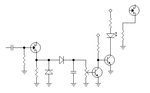
Hello, I have made an oscillator and I set it's ALC by feeding it's output to a diode rectifier and towards the oscillator again using a incadescent lamp and LDR combination.
The ALC works ok but I see amplitude variations, the amplitude goes up and down a little. How can I stabilize the loop for stable amplitude?
 

You've got an unstable system. You need to add some kind of compensation: PI, PID, feedforward, something.

What is the frequency of the oscillation? What is the amplitude?
 
  • Like
Reactions: neazoi

    neazoi

    Points: 2
    Helpful Answer Positive Rating
You've got an unstable system. You need to add some kind of compensation: PI, PID, feedforward, something.

What is the frequency of the oscillation? What is the amplitude?

Thank you Barry,
First of all, the transmitter operates at 1-30MHz.
The oscillation amplitude is about 0.5vpp @50R i.e the signal min and max values are so.
The oscillation frequency (how frequently the signal changes amplitude) depends on the signal frequency, but I would say it is about 2-8Hz or so.
I post a schematic of the ALC system to see.
The most right resistor is an LDR connected to the sourse of the oscillator FET, to change it's amplitude. Feedback is taken from the buffered oscillator output and put into the left most capacitor. Instead of the LED, I have used an incandescent lamp, as a means to remove these fluctuations. The lamp has slow responce, and the fluctuation frequency is reduced, but fluctuations are not eliminated.
One observation, is that the lamp completely removes fluctuations when it is more bright, I guess because the filament is hot enough and it cannot cool down instantly.
 

Attachments

  • Untitled.png
    Untitled.png
    17.5 KB · Views: 58
Last edited:

I'm not an expert at this, but I suspect the feedback approach (lamp and LDR) is your problem. As you've noted, the lamp response is pretty slow, probably too slow. It's like steering a boat: you turn the wheel and nothing happens, so you turn the wheel more, then the boat starts to turn, but you've already turned the wheel too much, so the boat turns too far, and you start the process over again in the opposite direction, continuously overshooting.
 

I'm not an expert at this, but I suspect the feedback approach (lamp and LDR) is your problem. As you've noted, the lamp response is pretty slow, probably too slow. It's like steering a boat: you turn the wheel and nothing happens, so you turn the wheel more, then the boat starts to turn, but you've already turned the wheel too much, so the boat turns too far, and you start the process over again in the opposite direction, continuously overshooting.

In fact I have found tha the use of the lamp reduced the problem. But it may be the other way round.
When I used a LED things were worst. Maybe I should change the value of the shunt capacitor after the diodes? It is 100nF now.
 

Trying a simple description in control system terms, you have a P controller and a PT3 or PT4 control system. It becomes unstable if the overall gain is too high and several pole time constants are in the same order of magnitude. Time constants are represented by rectifier filter, lamp and LDR response time and oscillator Q.

Taking most of the time constants as give, you can either increase the filter time constant to make it dominant and/or reduce the controller gain. As any P controller, your design involves a steady state error which increases with reduced gain. So you possibly want to change it to a PI controller with (almost) infinite DC gain and zero steady state error.
 
  • Like
Reactions: neazoi

    neazoi

    Points: 2
    Helpful Answer Positive Rating
Trying a simple description in control system terms, you have a P controller and a PT3 or PT4 control system. It becomes unstable if the overall gain is too high and several pole time constants are in the same order of magnitude. Time constants are represented by rectifier filter, lamp and LDR response time and oscillator Q.

Taking most of the time constants as give, you can either increase the filter time constant to make it dominant and/or reduce the controller gain. As any P controller, your design involves a steady state error which increases with reduced gain. So you possibly want to change it to a PI controller with (almost) infinite DC gain and zero steady state error.

Could you please give me some info about the PI controller? what is it?
 

ALC done for a 3 decades variable oscillator it is a challenge.
The constant amplitude at the output cannot be achieved without using a gain/buffer or attenuator stage controlled by ALC.
Perhaps for this wide frequency range is good to use a PIN attenuator controlled by the ALC circuit.
Generally PIN attenuators doesn't work very well below 10MHz, but you can try them because you are not looking for a high dynamic range attenuation.
BAR61 from Infineon has an application note where you can replace Vreg with your ALC voltage.

https://www.infineon.com/dgdl/Infin...n.pdf?fileId=db3a304314dca3890114fe4104c70a88
 
  • Like
Reactions: neazoi

    neazoi

    Points: 2
    Helpful Answer Positive Rating
  • Like
Reactions: neazoi

    neazoi

    Points: 2
    Helpful Answer Positive Rating
Status
Not open for further replies.

Similar threads

Part and Inventory Search

Welcome to EDABoard.com

Sponsor

Back
Top