Continue to Site

Welcome to EDAboard.com

Welcome to our site! EDAboard.com is an international Electronics Discussion Forum focused on EDA software, circuits, schematics, books, theory, papers, asic, pld, 8051, DSP, Network, RF, Analog Design, PCB, Service Manuals... and a whole lot more! To participate you need to register. Registration is free. Click here to register now.

ir2110 and 555 circuit does not working

Status
Not open for further replies.

fedaye

Member level 2
Joined
Mar 4, 2015
Messages
43
Helped
2
Reputation
4
Reaction score
2
Trophy points
8
Location
Istanbul
Activity points
273
Hey guys, can you help me, i want to drive inductance with 200 kHz by a half bridge like this. but the circuit is not working. can you tell me mistakes, i need this really, this is a thing about my graduation project.
20150304_193031.jpg20150304_193046.jpg
 

Hi,

there is no common ground.

IRF2110 Ground is only from 12V battery, but not from 15V battery.


Connect both grounds.

*********
Why you get no answers:
Because there is no detailed error description.

"It does not work" says nothing. Next time please describe what you expect. And what is NOT like expected.
Describe signals like the output of the NE555. Does it exist or not. Is it like desired. and so on....


Klaus
 
  • Like
Reactions: fedaye

    fedaye

    Points: 2
    Helpful Answer Positive Rating
thanks for your answer i am aware of it but unfortunately i do not have vast opportunities i do not have scope etc.
i will consider it
 

i have done but it did not work. LO is roughly 5.8 Volts and HO is roughly 11.5 Volts.(ir2110)
is this normal?
Vgs of the mosfets roughly 6 Volts also but there is not any switching
 

Hi,

i have done but it did not work. LO is roughly 5.8 Volts and HO is roughly 11.5 Volts.(ir2110)
is this normal?
Vgs of the mosfets roughly 6 Volts also but there is not any switching

How did you measure the voltages?

******

If you didi it with a DVM (giving averaged voltage values) the voltagews are correct.
LO is switching form 0V to about 12V. With a duty cycle of 50% i´d expect a value of about 6V. So 5.8V is OK.
HO is switching from 0V to about 25V. With a duty cycle of 50% i´d expect about 12.5V. So 11.5V may be correct.

You don´t have a scope... So how do you know it is not switching?

Klaus
 

i measured it by a multimeter. (dc value)
******
because mosfets and diodes are very cool really. and there are zero voltage values on the resistors between the gates and irf2110 (4.7 ohm). i will try scope at my school but i am hopeless :(
 

Hi,

mosfets are cool....

The diodes in your case allways should be cool, because there is (almost) allways one FET conductive. Therfore no current flow through the diodes. --> no heating.
The diodes are only conductive during FET (driver) deadtime when both MOSFETs are off. Usually only some 10s of nanoseconds.

*********

Zero volt at resistors...

The FET´s gate is very high ohmic. expect DC current of maybe some uA.
BUT there is a bit current peak at every switching edge. But very short - some 10 or 100 ns.
The resistors prevent from ringing.

*********

What FET current do you expect with your load? What type of FETs do you use?

Klaus
 

they are irfp460. The load is only an inductor, there is no separate resistor therefore i think the mosfets must be hot because of high current.(like a short circuit)
in past, i did a dc chopper and its supply was 12 Volts however that circuit's mosfet was very hot really.
 

Hi,

let´s see what the scope says...


Klaus
 

thanks a lot, maybe i will try it on wednesday then i will write here the results
 

Your DC supply voltages are wrong.
The 555 uses a +15V supply so its output high voltage is +13.5V which has destroyed the 74HC04. Why don't you use a Cmos 555 using a 5V supply instead?
The IR2110 has a logic supply of +15V but the logic from the 74HC04 is only +5V. Then the logic supply for the IR2110 must be +5V.
 

good point, audioguru.

Klaus
 

if try the scope and u ar gettinn any result. them try using sg3525 ic in replacement of 555timer.plz visit tahmid blog on ir 2110 drivers.
 

1- Your DC supply voltages are wrong.
2- The 555 uses a +15V supply so its output high voltage is +13.5V which has destroyed the 74HC04.
3- Why don't you use a Cmos 555 using a 5V supply instead?
4- The IR2110 has a logic supply of +15V but the logic from the 74HC04 is only +5V. Then the logic supply for the IR2110 must be +5V.
1, 2 and 4 are okay but i could not understand 3. Can you explain it for me? is cmos 555 a part that is different from 555
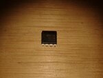
my 555 part is this:
20150307_143835.jpg
 

if try the scope and u ar gettinn any result. them try using sg3525 ic in replacement of 555timer.plz visit tahmid blog on ir 2110 drivers.

i have done it with sg3525 also.(on seperate pertinaxes) it is ready but it is not working also :(
 

Your photo shows an ordinary 555, a Cmos 555 has different spec's but has the same pin numbers and works the same.

Since you are using a 74HC04 inverter, its maximum allowed input voltage is 5V but you are destroying it with the +13.5V output high of an ordinary 555 that is using a supply voltage that is much too high at +15V.
If you use an ordinary 555 with a 5V supply then its output high voltage is only +3.5V which might not be high enough to feed the Cmos 74HC04 inverter.

Many manufacturers make Cmos 555 ICs with part numbers of LMC555, TLC555 and ICM7555. It is Cmos like the 74HC04 and with a 5V supply its output is 0V for low and +5V for high so one will work perfectly in your circuit.
 
  • Like
Reactions: fedaye

    fedaye

    Points: 2
    Helpful Answer Positive Rating
i got it. what about 6-8 Volts Vcc for my 555? then its output will become around 5 Volts and it is okey for 74hc04. is this true?
thanks a lot for your helps i need this really because this is a part of my graduation project that must be finished till May.

- - - Updated - - -

i think this means 2-6 volts required for 74hc04.
Adsız.jpg
 

Hi,

the HC04 needs about 0.7 x VCC (=3.5V for 5V VCC) for a valid high input signal
A HCT04 needs about 2V for a valid high input signal.

Klaus
 

i got it. what about 6-8 Volts Vcc for my 555? then its output will become around 5 Volts and it is okey for 74hc04. is this true?
I believe you are overcomplicating things now.

You can use a common 5V supply for LM555, 74HC04 and IR2110 VDD, as suggested by Audioguru. 555 output high level of 3.5- 4 V is sufficient for 74HC04 and IR2110.

Another point however is dead time. Presently the circuit provides only a very small amount of dead time by asymmetrical IR2110 delay which may be insufficient to drive the half-bridge safely.
 
  • Like
Reactions: fedaye

    fedaye

    Points: 2
    Helpful Answer Positive Rating
i will use 5-6 volts common supply for 555, 74hc04 and ir2110 (Vdd)
i will use 15 volts Vcc for ir2110.
i will connect all grounds each other.
driving the mosfets by 200 kHz is vital for me.
 

Status
Not open for further replies.

Similar threads

Part and Inventory Search

Welcome to EDABoard.com

Sponsor

Back
Top