Continue to Site

Welcome to EDAboard.com

Welcome to our site! EDAboard.com is an international Electronics Discussion Forum focused on EDA software, circuits, schematics, books, theory, papers, asic, pld, 8051, DSP, Network, RF, Analog Design, PCB, Service Manuals... and a whole lot more! To participate you need to register. Registration is free. Click here to register now.

Need for Class-A SE amplifier for HF

Status
Not open for further replies.

neazoi

Advanced Member level 6
Joined
Jan 5, 2008
Messages
4,122
Helped
13
Reputation
26
Reaction score
15
Trophy points
1,318
Location
Greece
Activity points
36,951
Hello, I need to build a small QRP amplifier for HF and I would like your thoughts suggestions/schematics on this. Below are the quick specs needed:

Frequency coverage: 1-30MHz
Power input: =<100mW
Power output: 1W minimum
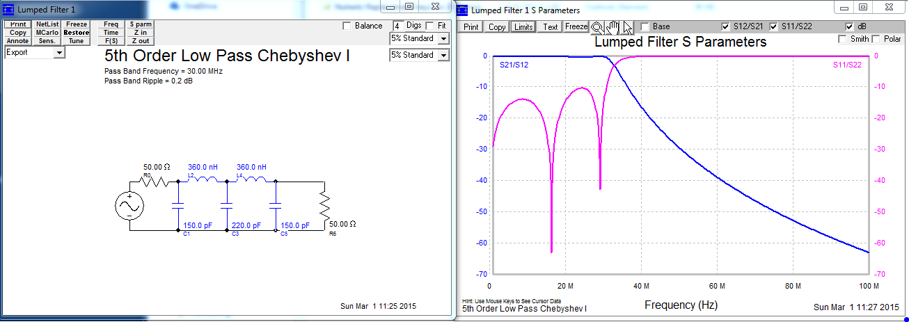
Output signal harmonics must be below -40dbc at all bands and no output filtering must be used (broadband)

Is that really so difficult to achieve?
 

Yes its difficult but not impossible. The gain will tend to fall off at the HF end. In 1968, where I worked we built 2-12MHZ manpack sets with 10 W PEP, with out any filtering except for tuning the whip aerial. Lots of transistors operating in class A (FETs were not invented then!).
A good place to start would be to use push pull FETs, this will give the lowest distortion. And locate a source of suitable ferrite cores for your transformers
Frank
 
  • Like
Reactions: neazoi

    neazoi

    Points: 2
    Helpful Answer Positive Rating
In any case, you could use an LPF to cut signals above 30MHz.


  • Like
Reactions: neazoi

    neazoi

    Points: 2
    Helpful Answer Positive Rating
Yes its difficult but not impossible. The gain will tend to fall off at the HF end. In 1968, where I worked we built 2-12MHZ manpack sets with 10 W PEP, with out any filtering except for tuning the whip aerial. Lots of transistors operating in class A (FETs were not invented then!).
A good place to start would be to use push pull FETs, this will give the lowest distortion. And locate a source of suitable ferrite cores for your transformers
Frank

Thanks all for your replies
I see... no wonder why I cannot find such circuits easily on the net.
I have tried some powerful transistors like the 2sc2166, but I had not much success with the harmonics levels.
I had previously tried some small push pull amplifiers but I could not get lower harmonics as well, despite the fact that I know theoretically they should eliminate some of them. Maybe my circuits were not well fine tuned.
My "ideal" circuit would be a power transistor operating as a class-A amplifier (at much lower output levels).
I cannot seem to find any schematic on the net, any help would be appreciated

The difficulty is coming from the wideband.Because optimum load is very variable with the frequency and this power level can not be maintaned simultaneously for whole band.
In additional to, in order to get low harmonics, the PA should work in very linear region.Input matching and overall gain ( 20dB) is also a big issue that impacts the PA.
Output filtering is inevitable.
 
  • Like
Reactions: neazoi

    neazoi

    Points: 2
    Helpful Answer Positive Rating
The difficulty is coming from the wideband.Because optimum load is very variable with the frequency and this power level can not be maintaned simultaneously for whole band.
In additional to, in order to get low harmonics, the PA should work in very linear region.Input matching and overall gain ( 20dB) is also a big issue that impacts the PA.
Output filtering is inevitable.

Even if wideband transformers are used at the output (and possibly at the input as well)?
 

Even if wideband transformers are used at the output (and possibly at the input as well)?
Input impedance is very variable, from which impedance to which impedance you will match ?? It will work somehow but ideal case can not be catched.
I have done a simple PA without input matching circuit so RL is bad.Optimum load impedance is found around 75Ohm for this PA @30MHz ( this is not constant and varies with frequency )and this should be transformed to 50 Ohm.As I have said before, wideband PAs are most difficult circuits especially in the case of when the bandwidth is more than 4 octaves.Neither input nor output cannot be matched properly due to very variable input impedance and required optimum load condition.If you apply feedback, input matching will be easier but gain will be rolled off.There are many constraints..
HF_OuputSpectrum.pngHF_PA.pngHF_VI.png
 
  • Like
Reactions: neazoi

    neazoi

    Points: 2
    Helpful Answer Positive Rating
I don't know how your setup for harmonics measurement looks, but I've seen many times that people accidentally inject at the input of the DUT a signal that already have high harmonics levels.
I mean, at level of 100mW (+20dBm), even the very expensive signal generators from Keysight (Agilent/HP) or R&S, have high harmonics levels at those frequencies. And the harmonics of the signal generator will be amplified by the DUT, and appears at the output in top of its generated harmonics.
For 1W (+30dBm) at the amplifier output, and about 15dB amplifier gain, you need the level of the fundamental harmonics at the DUT input to be below -25dBm (3mW).
 
  • Like
Reactions: neazoi

    neazoi

    Points: 2
    Helpful Answer Positive Rating
Input impedance is very variable, from which impedance to which impedance you will match ?? It will work somehow but ideal case can not be catched.
I have done a simple PA without input matching circuit so RL is bad.Optimum load impedance is found around 75Ohm for this PA @30MHz ( this is not constant and varies with frequency )and this should be transformed to 50 Ohm.As I have said before, wideband PAs are most difficult circuits especially in the case of when the bandwidth is more than 4 octaves.Neither input nor output cannot be matched properly due to very variable input impedance and required optimum load condition.If you apply feedback, input matching will be easier but gain will be rolled off.There are many constraints..

Thank you for your reply and your schematic.
Indeed accurate impedance matching is difficult in multi-octave amplifiers. However, practically, in the low frequencies involved here, do we really care too much about accurate impedance matching to 50R?
For example if I measure the output waveform of an amplifier at 50R and then at 1K and the waveform is a good sinewave in both cases, the losses from the impedance mismatching may be acceptable and they could possibly compensated by higher input signal driving levels (within acceptable distortion limits) or other techniques. After all the impedance mismatch mainly defines the energy transfer from one stage to the other as far as I know. I may be wrong though?

- - - Updated - - -

I don't know how your setup for harmonics measurement looks, but I've seen many times that people accidentally inject at the input of the DUT a signal that already have high harmonics levels.
I mean, at level of 100mW (+20dBm), even the very expensive signal generators from Keysight (Agilent/HP) or R&S, have high harmonics levels at those frequencies. And the harmonics of the signal generator will be amplified by the DUT, and appears at the output in top of its generated harmonics.
For 1W (+30dBm) at the amplifier output, and about 15dB amplifier gain, you need the level of the fundamental harmonics at the DUT input to be below -25dBm (3mW).

I have very carefully measured each stage of the mini transmitter that drives the discussed power amplifier, so that all harmonics are below -40dbc @100mW @50R. I have done this test in each stage, starting from the oscillator up to the last amplifier, so that to ensure that harmonics generated at a previous stage do not propagate (and amplified) in the next.
I was really considered on the fact you are talking about and thank you for mentioning this.
 

I don't know how your setup for harmonics measurement looks, but I've seen many times that people accidentally inject at the input of the DUT a signal that already have high harmonics levels.
I mean, at level of 100mW (+20dBm), even the very expensive signal generators from Keysight (Agilent/HP) or R&S, have high harmonics levels at those frequencies. And the harmonics of the signal generator will be amplified by the DUT, and appears at the output in top of its generated harmonics.
For 1W (+30dBm) at the amplifier output, and about 15dB amplifier gain, you need the level of the fundamental harmonics at the DUT input to be below -25dBm (3mW).

It's just a simulation buddy, the signal generator supplies a pure sinusoidal signal without any harmonics.The harmonics are generated by the amplifier itself.
 
  • Like
Reactions: neazoi

    neazoi

    Points: 2
    Helpful Answer Positive Rating
Buddy, actually my post was addressed to Neazoi and to his measurement setup. Be sure that I know that you are using a simulator.
 
  • Like
Reactions: neazoi

    neazoi

    Points: 2
    Helpful Answer Positive Rating
The simulation in post #7 illustrates that's it about to impossible to achieve -40 dBc harmonic distortion in a class A amplifier without strong linearization means, e.g. feedback. This is already the case for matched source and load impedance (assume 50 ohm in/out for simplicity), the situation won't be better if a variable load impedance has to be handled.

We have linear amplifiers covering the SW band or more as tools in the RF lab, an obvious property is rather high output stage quiescent power. So if you don't care about efficiency there can be a straightforward solution. Buf if you do, you'll most likely end up using output filters.

I have also implemented output stages for RFID test generators with power OPs (DSL drivers) that achieved high linearity by means of negative feedback. Power and frequency range is similar to the present design specification.

You've got the point, no interest about efficiency here, just broadband operation of the amplifier with as low harmonics as possible, without the need to use LPFs. The mini amplifiers in the transmitter (driver) are working near their current limits (running hot) and I have observer the best harmonics performance at these points. I think that something similar must be done for the power amplifier as well. An example would be very helpful.
 

You only need ~10dB of gain out of the thing, so I would have thought that something push pull based on a pair of small RF power transistors or mosfets with emitter/source degeneration and the input capacitance swamped with a resistor should get you close.

RF feedback taken from a single turn winding on the DC injection bifiliar will help further.
Not easy, and the magnetics will be critical, but it should be just about doable.
Design the collector/drain match to keep well away from saturation obviously.

They have poor isolation, but I am actually wondering about a norton (as in common base, transformer feedback) amp for this use.

Regards, Dan.
 
  • Like
Reactions: neazoi

    neazoi

    Points: 2
    Helpful Answer Positive Rating
You only need ~10dB of gain out of the thing, so I would have thought that something push pull based on a pair of small RF power transistors or mosfets with emitter/source degeneration and the input capacitance swamped with a resistor should get you close.

RF feedback taken from a single turn winding on the DC injection bifiliar will help further.
Not easy, and the magnetics will be critical, but it should be just about doable.
Design the collector/drain match to keep well away from saturation obviously.

They have poor isolation, but I am actually wondering about a norton (as in common base, transformer feedback) amp for this use.

Regards, Dan.

I have tried push pull based on discrete transistors **broken link removed** and ca3083 arrays and they both worked, but I was not happy with the harmonics levels.
I have never seen a norton in a power amplifier configuration before.
 

Status
Not open for further replies.

Part and Inventory Search

Welcome to EDABoard.com

Sponsor

Back
Top