Continue to Site

Welcome to EDAboard.com

Welcome to our site! EDAboard.com is an international Electronics Discussion Forum focused on EDA software, circuits, schematics, books, theory, papers, asic, pld, 8051, DSP, Network, RF, Analog Design, PCB, Service Manuals... and a whole lot more! To participate you need to register. Registration is free. Click here to register now.

Electronic circuit design suggestion

Status
Not open for further replies.

Gaber2611

Member level 1
Joined
Apr 21, 2012
Messages
41
Helped
0
Reputation
0
Reaction score
0
Trophy points
1,286
Activity points
1,677
Hello everybody,

i am working on electronic circuit design, which takes audio input up to 1khz waveform, "the audio wave forms are different and at different frequencies", its maximum frequency is 1khz

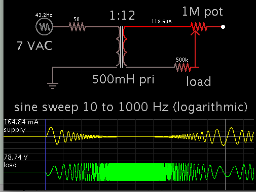
and required to output the same frequency at voltage from 20-450v , at very low ampere " Doesn't exceed 100 Micro-ampere"

also the output voltage needs to be controlled, up/down buttons, to increase and decrease the output voltage, and displayed with 0-100 counter on LCD screen

any suggestion for simple design to follow for this circuit?,

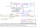
im thinking of using micro-controller, for controlling the voltage and the LCD display, but i hope to avoid using the micro-controller, cause im not familiar with the programming, and for the high voltage output im using transformer, so any suggestion?, how you would design this circuit?, which block diagram you would follow?

Note: the circuit will be powered by 2AA batteries of 3dcv, 2100MAH

will appreciate your replies a lot,
Thanks in advance
 

What is the MINIMUM frequency? If it's close to DC, your transformer approach won't work, and you'll have to look at using a high-voltage amplifier. But assuming you can use a transformer and don't want to use a processor, you could use a digital potentiometer to set your voltage level. They make simple, pushbutton-controlled digital pots. Then you need to display something on your display. Does the "100" just correspond to full-scale, or do you need to display actual voltage?

You could use an up/down counter (that would be controlled by the push buttons) to drive the input to the display. Or you could also use the counter output to digitally control the amplitude (you could use analog switches and resistors).
 

Hi barry,

Thanks for your response, i searched more yesterday, and i could find very close design to my design specifications, with micro-controller, and LCD display, with the source code, but i will just have to configure the code as i need

the 100 , refers to full scale , yes, and no there is no need to display the actual voltage

the minimum frequency is 10hz, why not the transformer won't give that output high voltage?, if the turn ratio of it, achieve the output voltage why it won't give the desired output voltage?, and if so, what is the solution in your opinion?

Thanks again for your response
 

Think of it this way: if you put DC into the primary, you'll get nothing out of the secondary. The efficiency of the transformer drops off as the frequency gets lower. You just need to make sure you get a transformer that has the desired performance over your frequency range.
 

i won't apply DC voltage to the primary coil of the transformer, i will apply sine wave form at frequencies range from 10-1khz, and with a specific turn ratio of the transformer i can get the desired voltage

do you suggest any circuit for converting the amplified audio signal to sine wave form at the same frequency of the audio signal and then apply to the transformer?
 

What do you mean by 'convert audio signal to sine wave at same frequency'? All signals are composed of sine waves. Do you mean to extract the fundamental frequency?
 

If you take this as a purely theoretical problem, a small audio amplifier followed by a transformer could do it. But considering parameters of real audio transformers, it doesn't work. And I presume you won't be able to make the transformer or find anyone who knows to make it.

The only practical way to generate the high audio voltage is a DC/DC converter supplying a high voltage amplifier. You can search for electrostatic headphone amplifiers to get an idea how it's possible.

If the low input power is feasible or not depends on the design details. Not impossible, but demanding in my view. I doubt that you have the required electronic design knowledge for this project.

The load should be more clearly specified. 450 V single ended (ground referred) or differential? What is the load specification in impedance terms (equivalent RC circuit)?
 

well, i am new to the electronic circuits design, and i am mainly mechanical engineer, but with some good knowledge and interest into electronics which i believe that it will help me finishing such a project " hopefully", with some search and experts help, as you FvM and barry

FvM the load will be connected by electrodes to human, to treate pain in the nerves, called stimulator device, do you have any idea about it?
" Here i am more clear"

and the load will be LC equivalent circuit, " Look at that stimulator output, and i need it like this "

transcutaneous-electrical-nerve-stimulator-circuit-diagram-1366318226.GIF

so the design plan to use high voltage amplifier and connect it a transformer and controlling the amplifier by micro-controller and digital potentiometer?

i just thought of the transformer to isolate the circuit from the load, as it will be medical device and that's important

i attached also block diagram of the design im working on, take a look, and let me know if you have any comment about it

and i appreciate your both help
 

Attachments

  • updated block diagram.bmp
    1.6 MB · Views: 58

I'm still confused about the "sine wave converter" part of your design. What, exactly, are you converting? You've got an "audio" input and a "sine wave" output. What's the transfer function ? In other words, what's the relationship? Is it a filter? An FFT? A correlator?
 

I know medical EMS (electrical muscle stimulation) devices which are using short pulses at low repetition rate, the circuit in post #8 seems only roughly related to it and your block diagram even less. I don't recognize a reasonable medical purpose.

Technically, your transformer solution doesn't work at lower audio frequencies, as already mentioned.
 

Thanks again for your care to response

here is me configured the block diagram, according to the information you told me about, and i think it should work this time, let me know FVM if the transformer will work this time, and if not, what component you see i have to replace the transformer with to give the desired output voltage and frequencies
 

Attachments

  • updated block diagram2.PNG
    updated block diagram2.PNG
    27.6 KB · Views: 62

My brother has a storebought unit that delivers voltage to the skin. I suppose it is several tens of V. Its name is muscle stimulator, or muscle relaxer. The sensation is pleasant. If I had sore muscles I think I'd try to build one of these myself.

Your project is a combination of many parts. Each one is a project in itself. Each will need to be individually designed, constructed, tested.

As for the transformer, here is my simulation showing what values could work. Due to your 10 Hz spec, the primary needs to be on the order of 1/2 Henry.


You should make it impossible for the output to go over a certain amplitude. There is a safe level, in a range between 50 and 100V, if you plan to contact human skin.
 

how much ampere is your brother muscle stimulator Brad?,

as the output amperes for my circuit design won't exceed 100 micro-ampere, " Very low ampere", and high voltage
 

Status
Not open for further replies.

Part and Inventory Search

Welcome to EDABoard.com

Sponsor

Back
Top