Continue to Site

Welcome to EDAboard.com

Welcome to our site! EDAboard.com is an international Electronics Discussion Forum focused on EDA software, circuits, schematics, books, theory, papers, asic, pld, 8051, DSP, Network, RF, Analog Design, PCB, Service Manuals... and a whole lot more! To participate you need to register. Registration is free. Click here to register now.

Oscillation in ATE testing for K0 test

Status
Not open for further replies.

sabahking86

Newbie level 3
Joined
Feb 26, 2015
Messages
4
Helped
0
Reputation
0
Reaction score
0
Trophy points
1
Activity points
35
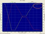
I was writing the ATE test program at ETS364 for device VNQ5E050MK-E in my company. In one test known as k-factor i found some oscillation in the waveform. This test is perform such that we ramp the current from drain to source, and current sense will monitor the current at output. The formula is that kfactor =Iout / Isense. However, for this test during i perform at high current (k1 and K2) it is ok, the oscillation is only happening on K0 (low current). Refer the image.

My question is that
a) at what scenario of the weakness of hardware can cause this type of oscillation at low current but not high current.
b) any method in eliminate the oscillation?
 

I am not familiar with the k factor test and I see Terradyne have come a long way.

Please repost your photo... not found..

But "Some oscillation" indicates either stray RF or an impedance problem with fixture inductance.

Although a current source is high impedance the load I presume is just the current sense R and Vds at high ramp current. In other works a low impedance load measurement.
I would expect a purely resistive response unless bandwidth limitations are involved.

At low currents, the ringing suggests either the ramp is too fast OR some stray reactance using a high impedance low current. Now the circuit impedance is high,
Both stray capacitance and inductance affect the waveform.

If the oscillations also occur with a pulse load test, with ringing after shutoff, that would confirm this is a signal integrity issue.

Prevention depends on finding the cause and attention to controlled impedances and shielding.

I suspect k factor is useful for testing semi's on large ATE to avoid the layout bandwidth issues of a step pulse or an impulse as the ramp is the 2nd integral of the flat frequency spectrum.
 

K0.jpg

Device_datasheet.png

Sorry that iam newbie in this forum. Here is the waveform capture from digitizer at ETS364, it should be more or less the same if captured by oscilloscope. I also including the print screen of the test which I am tested in datasheet.

The k factor is used to monitor the current at output in application for this device. FOr sure i dont know what is happening on the hardware (test jig and probecard) which caused the oscillation/ringing. For the hardware it is worked fine for other tests in datasheet during the ATE testing.
 

It's hard to read the current on Io in red for Ko but it looks like 50mA out 20uA in for Ko = 2500 which is in spec but hard to measure with the ramp step decaying to 0 with oscillation and would require averaging. But no time scale.

Specs for Ko at 50mA out are 1050 to 3170 are equivalent to 2110 +/- 50%, so accuracy drops at at very low currents.

What frequency? It looks like a combination of the ATE ramp test being marginal with the step ramping down after 450 data points when the current ramp reaches near zero.

Did you use their test board PowerSSO-24 PC board ? ( I guess not if on ATE fixture. )

I think the resolution may be just a cap on I sense. ( Cext) and testing a temporary ground plane as the transistor current mirror ramps down to zero for K0 test.
 

Status
Not open for further replies.

Similar threads

Part and Inventory Search

Welcome to EDABoard.com

Sponsor

Back
Top