Continue to Site

Welcome to EDAboard.com

Welcome to our site! EDAboard.com is an international Electronics Discussion Forum focused on EDA software, circuits, schematics, books, theory, papers, asic, pld, 8051, DSP, Network, RF, Analog Design, PCB, Service Manuals... and a whole lot more! To participate you need to register. Registration is free. Click here to register now.

Help for opto resistor

Status
Not open for further replies.

flavitie

Newbie level 4
Joined
Feb 25, 2015
Messages
5
Helped
0
Reputation
0
Reaction score
0
Trophy points
1
Activity points
39
Hi everybody, I am not sure if this post follows the guidelines of the forum nor if it is in the right group, I apologize if not.
I have no clue of electronics design (I work on software design) and I need help to solve the following:

I have to build a sort of fingertip keyboard using light detecting sensor, i.e. to detect when a finger covers up a senor.
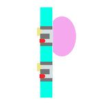
The sensor (photo resistor or diode or similar) is mounted on a plastic box as depicted in the attached image where>
yellow is the sensor, cyan is the plastic box, dark grey is opaque coating, blue is water (right part is outside, left part inside the waterproof box), pink is fingertip.
the sensor should be connected to a digital Input port of the raspberry Pi, when the finger covers the sensor the port should detect a a logic High, otherwise low.
there are 10 of such sensor in the box.

Could anyone suggest a design? I would need a complete schematic and component list since I have no electronics knowledge.


schema.jpg


Thanks a lot for any support!

F.
 

Being under water makes the problem more complicated. If you could guarantee that enough light fell through the hole to the sensor when it was NOT covered, it would be very easy and cheap. You could do it with nothing more than a light dependant resistor (LDR) and a fixed resistor per input. Covering the hole would block the light and cause a voltage change you could monitor. However, with water around it and maybe proximity to other sensors, that method may be unreliable. The 'fall back' reliable method is to provide a source of light adjacent to the sensor and look for reflected rather than transmitted light. If the sensor is on it's own, you could line the hole with a black sleeve to prevent light entering sideways then suround the whole (cyan) area with a single back light, if you have several sensors close together you would have to be careful that you didn't reflect light into the hole of an adjacent sensor.

You can get reflective opto switches, they are basically an IR LED and an IR sensor mounted side by side in a single body. They are both directional and face the same way so they look into the space in front of them. When an object passes before them, some of the LED light is reflected back into the sensor and it changes logic state. You can read that signal back into the Raspberry Pi. I'm not sure what would happen if you immersed it's face directly in water though. They are waterproof but there may be enough light scatter in the water to fool the sensor, it might depend on the clarity and purity of the water so you would need to experiment.

Brian.
 
Brian, thanks for your reply.
I think I understand your point, would something like the attached modified diagram work, where:
yellow is the sensor, red is led light, cyan is the plastic box, dark grey is opaque coating, light grey is transparent glue, blue is water (right part is outside, left part inside the waterproof box), pink is fingertip?

In such case which circuit/components would you use having a 5Vdc power source and with a desired output to the raspberry I/O port of 3,3V high=finger covering hole / 0V low= finger not covering hole? (sorry for the very basic question)

Thanks again!

Being under water makes the problem more complicated. If you could guarantee that enough light fell through the hole to the sensor when it was NOT covered, it would be very easy and cheap. You could do it with nothing more than a light dependant resistor (LDR) and a fixed resistor per input. Covering the hole would block the light and cause a voltage change you could monitor. However, with water around it and maybe proximity to other sensors, that method may be unreliable. The 'fall back' reliable method is to provide a source of light adjacent to the sensor and look for reflected rather than transmitted light. If the sensor is on it's own, you could line the hole with a black sleeve to prevent light entering sideways then suround the whole (cyan) area with a single back light, if you have several sensors close together you would have to be careful that you didn't reflect light into the hole of an adjacent sensor.

You can get reflective opto switches, they are basically an IR LED and an IR sensor mounted side by side in a single body. They are both directional and face the same way so they look into the space in front of them. When an object passes before them, some of the LED light is reflected back into the sensor and it changes logic state. You can read that signal back into the Raspberry Pi. I'm not sure what would happen if you immersed it's face directly in water though. They are waterproof but there may be enough light scatter in the water to fool the sensor, it might depend on the clarity and purity of the water so you would need to experiment.

Brian.
 

forgot the diagram... here it is.

Being under water makes the problem more complicated. If you could guarantee that enough light fell through the hole to the sensor when it was NOT covered, it would be very easy and cheap. You could do it with nothing more than a light dependant resistor (LDR) and a fixed resistor per input. Covering the hole would block the light and cause a voltage change you could monitor. However, with water around it and maybe proximity to other sensors, that method may be unreliable. The 'fall back' reliable method is to provide a source of light adjacent to the sensor and look for reflected rather than transmitted light. If the sensor is on it's own, you could line the hole with a black sleeve to prevent light entering sideways then suround the whole (cyan) area with a single back light, if you have several sensors close together you would have to be careful that you didn't reflect light into the hole of an adjacent sensor.

You can get reflective opto switches, they are basically an IR LED and an IR sensor mounted side by side in a single body. They are both directional and face the same way so they look into the space in front of them. When an object passes before them, some of the LED light is reflected back into the sensor and it changes logic state. You can read that signal back into the Raspberry Pi. I'm not sure what would happen if you immersed it's face directly in water though. They are waterproof but there may be enough light scatter in the water to fool the sensor, it might depend on the clarity and purity of the water so you would need to experiment.

Brian.
 

Attachments

  • schema2.jpg
    schema2.jpg
    15.5 KB · Views: 40

In contrast to the transmissive sensor that relies on the presence of ambient light, a simple (DC) reflective sensor requires ambient not to exceed a certain intensity. No idea if this can be assured in your application. Reflective sensors are available as single component comprised of an IR LED and a phototransistor and widely used home, office and industry appliances, e.g. paper presence detection in printers.

If ambient light level is too high, you better go for modulated IR with selective AC light detection. I believe, there are some self-contained modulated IR reflective sensors available.

- - - Updated - - -

Of course you can make your own reflective AC sensor circuit, like the below shown example:

 
Both those sensors would be suitable, the first one would be my choice because it is smaller and you don't need the longer range offered by the second one. They do have IR filters on the sensors which help to filter out some ambient light although I'm not sure how IR travels through water or how close any IR sources may be so I can't predict if you will have problems in that regard. Intuitively I don't think ambient IR would be a problem but explaining (as you say you have no electronics knowledge) what FvM wrote about: There is a way to improve reliability when the reflected light may be weak against other illumination, you make your own source of light flash rapidly (hundreds or thousands of times a second) so it stands out from the relatively steady background level. By frequency filtering the output of the sensor you can selectively pick out your own signal from all the others. It's the method used by remote control units so your TV doesn't change channel when you switch the room lights on for example.

You can try the reflective sensor first and if you find it unreliable you have the option of adding the flash/filter circuit afterwards, the same sensor can be used in place of the TIL78 and TIL74 in the diagram FvM showed.

Brian.
 
cool. I'll find a couple of those sensors and build a prototype to do some testing in water.
Thanks to both of you, you have been very helpful, F.


Both those sensors would be suitable, the first one would be my choice because it is smaller and you don't need the longer range offered by the second one. They do have IR filters on the sensors which help to filter out some ambient light although I'm not sure how IR travels through water or how close any IR sources may be so I can't predict if you will have problems in that regard. Intuitively I don't think ambient IR would be a problem but explaining (as you say you have no electronics knowledge) what FvM wrote about: There is a way to improve reliability when the reflected light may be weak against other illumination, you make your own source of light flash rapidly (hundreds or thousands of times a second) so it stands out from the relatively steady background level. By frequency filtering the output of the sensor you can selectively pick out your own signal from all the others. It's the method used by remote control units so your TV doesn't change channel when you switch the room lights on for example.

You can try the reflective sensor first and if you find it unreliable you have the option of adding the flash/filter circuit afterwards, the same sensor can be used in place of the TIL78 and TIL74 in the diagram FvM showed.

Brian.
 

Status
Not open for further replies.

Part and Inventory Search

Welcome to EDABoard.com

Sponsor

Back
Top