Continue to Site

Welcome to EDAboard.com

Welcome to our site! EDAboard.com is an international Electronics Discussion Forum focused on EDA software, circuits, schematics, books, theory, papers, asic, pld, 8051, DSP, Network, RF, Analog Design, PCB, Service Manuals... and a whole lot more! To participate you need to register. Registration is free. Click here to register now.

Problem getting results from Peak Detector circuit

Status
Not open for further replies.

RDL

Newbie level 3
Joined
Feb 21, 2015
Messages
4
Helped
0
Reputation
0
Reaction score
0
Trophy points
1
Location
Edmonton, Canada
Activity points
26
Further to the old discussion on https://www.edaboard.com/threads/298751/
I tried to use the first circuit illustrated. I have modified the drawing to illustrate the pins used and to show 9 Volts IN.
eleccircuit Peak detector 2.jpg

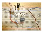
A 40 KHz signal input is giving no output, on the scope, which indicates a screw-up. Also attached is a photo of the breadboard to give you a better understanding of my problem. It may appear that the bottom 10K Resistor is in the wrong hole but the lead does bend inwards to connect with the Input which then leads to #2 of the CA3140.
Peak Detector CA3140 Annotated.jpg

After the laughter ceases is it possible to find out what is wrong or what I should measure?

Raymond
 

I fear the author from www.eleccircuits.com has problems with reading datasheets. He definitely mixed-up '+' and '-' input of the OP, creating positive instead of negative feedback.

- - - Updated - - -

O.K., it's not the author. There are no pin numbers in the original circuit. You better review a datasheet.
 
  • Like
Reactions: RDL

    RDL

    Points: 2
    Helpful Answer Positive Rating
I fear the author from www.eleccircuits.com has problems with reading datasheets. He definitely mixed-up '+' and '-' input of the OP, creating positive instead of negative feedback.

- - - Updated - - -

O.K., it's not the author. There are no pin numbers in the original circuit. You better review a datasheet.

You are correct it was my mistake. Now, I exchanged the Input + to the #3 pin and #2 to the R2 10K.

The Output signal is still a flat line. A new CA3140 was inserted but there was no improvement.

- - - Updated - - -

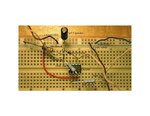
This is the corrected Circuit Pin # and the revised breadboard that corrects the #2 and #3 Pin wiring error. The breadboard arrangement is still not giving an Output to the scope. Is there a measurement that I can attempt to give more information?

eleccircuit Peak detector 2.jpg

Peak Detector CA3140 Annotated 2.jpg
 
Last edited:

The CA3140 is very old. Its inputs do not work if they are within 2.5V from ground in this circuit. Its gain is low at 40kHz.
You need an opamp that has inputs that work when their voltage is at 0V like a TLE2141 or many other modern opamps. Its gain is pretty high at 40kHz.
 
  • Like
Reactions: RDL

    RDL

    Points: 2
    Helpful Answer Positive Rating
It's true that CA3140 isn't best choice for a 40 kHz peak detector. On the other hand, the circuit parameters have to be adapted to the OP GBW and output impedance. Simply using an OP with higher GBW can cause overshoot of the peak detector and respective systematical error.

A substantiated circuit design would start with a complete specification.
 

I would add a transistor as an emitter-follower at the output of the opamp to provide lots of current to quickly charge the capacitor since the opamp by itself has a low output current.
 
  • Like
Reactions: RDL

    RDL

    Points: 2
    Helpful Answer Positive Rating
Thank you for the response. I did try a TLE2141 but the circuit did not peak detect and hold. I concur with FvM that there is a need for a "substantiated circuit design" and so called in an expert to do the architecture.
 

Status
Not open for further replies.

Similar threads

Part and Inventory Search

Welcome to EDABoard.com

Sponsor

Back
Top