Continue to Site

Welcome to EDAboard.com

Welcome to our site! EDAboard.com is an international Electronics Discussion Forum focused on EDA software, circuits, schematics, books, theory, papers, asic, pld, 8051, DSP, Network, RF, Analog Design, PCB, Service Manuals... and a whole lot more! To participate you need to register. Registration is free. Click here to register now.

RMS vlaue of fundamental (100Hz) current in offline, PFC'd flyback output diode?

Status
Not open for further replies.
T

treez

Guest
Hello,
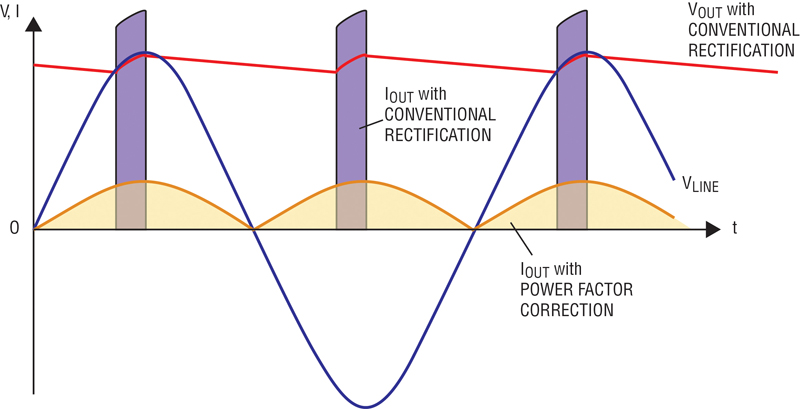
The below waveform shows the current in the secondary diode of an offline , power factor corrected flyback.
Clearly there is a strong 100Hz fundamental.
Being so low in frequency, this will cause much heating in the output electrolytic capacitor.
However, what is the RMS value of the 100Hz fundamental?…..is it the same value as the RMS value of the overall current? (in LTspice this comes out as 1.78A RMS)
LTspice gives the average value of this current as 1.16Amps.

So the question is, what is the RMS value of the 100Hz fundamental current?


LTspice simulation attached ("PFC flyback"), also the diode current waveform over 10ms is shown, and a zoomed in version of it.
(also attached is the “TIME FILE.txt”, which needs to be in the same folder as the simulation.

Diode current.jpg

Diode current _zoomed in.jpg
 

Attachments

  • TIME FILE.txt
    609.5 KB · Views: 59
  • PFC flyback.txt
    2.9 KB · Views: 60

An "Ideal" sawtooth of amplitude A peak-peak has an RMS value
Vrms= 2A/√3

But your waveform is zero for ~10% of the time, so it will be 10% less.
 
  • Like
Reactions: treez

    T

    Points: 2
    Helpful Answer Positive Rating
Yes, but this, i'll call it "gappy sawtooth" wave exists in an envelope of 100Hz...and its the rms value of this 100Hz envelope that is of interest.
 

Considering the operation principle of a PFC power supply, it's easy to predict the secondary current. You don't need a simulation to do it, just pencil and paper.
 
  • Like
Reactions: treez

    T

    Points: 2
    Helpful Answer Positive Rating
I know what the secondary current is (its as in the above jpeg in post #1).
The AC RMS current of this = sqrt(I(RMS)^2 - I(average)^2)

so the AC RMS ,which flows in the output cap, is sqrt(1.78^2-1.16^2) = 1.35A (AC RMS).

The problem is, what proportion of this 1.35AC RMS is at the fundamental frequency of 100Hz?.......(we need to know because that is what is going to heat the output capacitor up more, because as you know, ESR is higher at low frequency)
 

In case of an ideal PFC supply the low frequent AC component(everything besides pwm frequency) is pure 100 Hz. And it's swinging around Iavg down to zero, in other words Irms,100Hz is 0.71*Iavg.
 
  • Like
Reactions: treez

    T

    Points: 2
    Helpful Answer Positive Rating
Thanks, and do you agree that due to this 100Hz component of the ripple current in the output cap, this PFC supply presents additional heating problems for the output cap? ..(as opposed to if it had been done as a non PFC flyback constant current led driver, without the 100Hz component in the secondary cap current?
 

Of course. In a PFC design the secondary capacitor does all required energy storage between pulsating input power and continuous output power.
 
  • Like
Reactions: treez

    T

    Points: 2
    Helpful Answer Positive Rating
Yes I agree, but what I have found a few minutes ago, by taking the FFT of the post #1 waveform, is that the 100Hz fundamental component of the post#1 waveform , has an RMS value less than half of the actual overall waveform's RMS.

This astounds me because it has a strong half-sinusoid appearance. It actually means that the AC RMS current component at 100Hz, in the output cap is not as bad as I thought it would be.
....woops, actually I correct myself, I forgot to note that their is also much energy around 100Hz...say 80 to 120Hz, so in fact there is a strong low frequency component after all.....bad news for the output cap.
 

THe PFC Dielectric doesn't care if the ripple current is 100 Hz or 200KHz if the amplitude is the same
...unlike Eddy Currents in magnetics and conductors.

The Cap heat loss is still P= I²(t)* Rc

for Rc=ESR of Cap


As you know,


1384947039P234-Fig2.jpg


The job is to reduce the peak currents of 100Hz diode bridge which for 10% voltage ripple might be 10x the average current for 10% duty cycle.

Since PF =1 represents a linear in phase current like after a line filter the supply>load current will look like a 50Hz rectified sine like a resistive load.

My calculations need checking but, look like this.

Converting your waveforms;
Peak-Peak Current A(p-p) to RMS current A(rms)


RMS Sawtooth = 1/(2√3) * A(p-p)
Deadband = 22% duty cycle or 78% of result.
RMS Full Wave Rectified Sine = 1/(√2) * A(p-p)
 
  • Like
Reactions: treez

    T

    Points: 2
    Helpful Answer Positive Rating
Status
Not open for further replies.

Similar threads

Part and Inventory Search

Welcome to EDABoard.com

Sponsor

Back
Top