Continue to Site

Welcome to EDAboard.com

Welcome to our site! EDAboard.com is an international Electronics Discussion Forum focused on EDA software, circuits, schematics, books, theory, papers, asic, pld, 8051, DSP, Network, RF, Analog Design, PCB, Service Manuals... and a whole lot more! To participate you need to register. Registration is free. Click here to register now.

High side mosfet driving problem - IR2101

Status
Not open for further replies.

Bianconero

Newbie level 6
Joined
Dec 22, 2014
Messages
11
Helped
1
Reputation
2
Reaction score
1
Trophy points
3
Activity points
92
Hi, I designed a simple half bridge circuit using popular FET driver IR2101 (switching freq. around 500 Hz, drain current about 250 mA, supply voltage about 12 V):

IMG_20150216_134751.jpg

Of course I have resistive load connected between the VS node and ground, just forgot to draw it.
This is a part of a bigger schematic, but the bridge circuit doesn't work as I expected. When the high side FET is on, the voltage drop across it (drain-source voltage) is about 2.1 V. When the low side FET is ON, everything is OK - the Vds voltage of it is around 0 V.

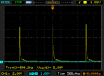
Voltage between LO and GND looks pretty good - a square wave from 0 to 12 V. Voltage between HO and VS looks exactly like this:
NewFile0.png

I guess that the problem is caused by improper driving the high side, ie. the bootstrap circuit. The gate voltage drops and the high side FET works in its linear region. What could I do to force it to saturate? Is the 1k G-S resistor a problem? I read that there should be such resistor to prevent FETs from various failure types.
 
Last edited:

What's the duty cycle of your rectangular 500Hz signal? Seems like the bootstrap capacitor doesn't have enough time (or enough current) to charge. What's the voltage across the bootstrap capacitor? It has a high ripple, I suppose.

You should try a faster bootstrap diode, a decoupling capacitor across Vcc and a smaller gate series resistor.

- - - Updated - - -

Seems like you're not using any dead time between low-side/high-side signals. If that's the case, you're encountering a shoot-through when you're trying to switch on the high-side MOSFET.
 

The waveform makes no sense for a 47 uF bootstrap capacitor, with or without 1 k gate-source resistor. Eiher the capacitor isn't connected or some part is defective.

The 1N4148 will have problems to stand the capacitor charging peak currents. You should use a fast 1A rectifier diode instead.
 
Scope Vb signal, if excess sag, remove 1k from high side.

The signal (HO-VS) has pulse width PW50<50us which means low side driver and mainly 1N4148 Diode resistance is <1Ohm with 47uF Cap,

...but the 8.9V spike every 2 ms suggests Vb decay rate on 47uF is too fast.

more scope signals and verify passive values will tell the answer.
 
Looking at the scope image, seems like the driver outputs an enough voltage at the begining then it fall back quickly.

1. The only bootstrap capacitor in the circuit is the smaller one (330nF), as @FvM has suggested.

2. A shoot-through occurs, which (in case of a weak 12V power supply or in absence of a decoupling capacitor) could cut the driver Vcc voltage so the control signal is turned off (despite the bootstrap capacitor being fully charged).

(the bootstrap capacitor only feed the output stage of the high-side block of the IR2101.)

- - - Updated - - -

(if the Vcc is bellow 9V, the undervoltage lockout is activating)
 

I don't believe that point 2 is a possible scenario for the shown waveform. A supply voltage sag can't cause intermediate output voltage at the highside. The output stage would be either on or off. You can see that it's finally turned off after about 400 µs.
 

Maybe it's just the gate capacitor slowly self discharging.

The shoot-through occurs only after the high-side MOSFET has turned ON, so there's no intermediate output voltage at the high-side but the normal operation (till the undervoltage lockout is activating).
 

You were right guys, the technician I asked to build a prototype of this circuit soldered the positive electrode of the 47 uF cap to the gate of the FET, between resistors, instead of connecting it to VB. Doh! I haven't checked that out assuming he did it right. Now everything seems to be fine.
And yeah, I'm using pretty long deadtime, around 1 us.

One question: is the 1k resistor needed in such circuit or the active pulldown of the IR2101 makes it useless?
 

One question: is the 1k resistor needed in such circuit or the active pulldown of the IR2101 makes it useless?
Some authors are ongoingly suggesting this pull-down resistors although you don't find it in any manufacturers application note or datasheet. The problem of increased bootstrap current demand has been already addressed.

In fact there's a very small gate driver supply voltage range where the push-pull driver isn't yet driving low and the MOSFET might be already steered to on-state. I think, if at all, this can only happen with logic-level MOSFETs. In my view, the pull-down resistor suggestion isn't clearly substantiated.
 

The 0.33uf capacitor will discharge into the 1.1k load in 330us. For a frequency as low as 500Hz the capacitor must be much larger.
 

Maybe you missed the point but he actually designed a 47uF capacitor in parallel with the 330nF one (though it was soldered in a wrong way by a technician).
 

Some authors are ongoingly suggesting this pull-down resistors although you don't find it in any manufacturers application note or datasheet. The problem of increased bootstrap current demand has been already addressed.

In fact there's a very small gate driver supply voltage range where the push-pull driver isn't yet driving low and the MOSFET might be already steered to on-state. I think, if at all, this can only happen with logic-level MOSFETs. In my view, the pull-down resistor suggestion isn't clearly substantiated.

My understanding for pull down resistor is a fail-safe mechanism. I personally place it not after gate resistor, but before. If the driver burns up, without any short-circuited outputs, pull down makes sure the gate is turned off. Oherwise parasitics may turn on gate.

DRVOUT---/\/\/\/\----gate
|
|-/\/\/\/\----source
 

Status
Not open for further replies.

Part and Inventory Search

Welcome to EDABoard.com

Sponsor

Back
Top