Continue to Site

Welcome to EDAboard.com

Welcome to our site! EDAboard.com is an international Electronics Discussion Forum focused on EDA software, circuits, schematics, books, theory, papers, asic, pld, 8051, DSP, Network, RF, Analog Design, PCB, Service Manuals... and a whole lot more! To participate you need to register. Registration is free. Click here to register now.

ESR of electrolytic capacitors is too high?

Status
Not open for further replies.
T

treez

Guest
We have five 220uF, 400V electrolytic capacitors in parallel (Nichicon UVR2G222M).

UVR2G222M capacitor datasheet:
http://nichicon-us.com/english/products/pdfs/e-vr.pdf

They are being used in a capacitor discharge unit which acts as a LED flasher.

This capacitor bank is charged up to 333V, and then, every second, they are discharged with a 1 Amp discharge current for 0.3 seconds, then during the proceeding 0.7 seconds they are charged back up to 333V with a 429mA charge current. This happens repeatedly.

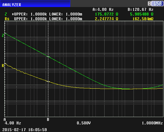
thus the frequency of the ripple current in each of these capacitors is very low, (1 Hertz)

The tan(delta) for these capacitors is 0.25. Therefore, the ESR is tan(delta) * Xc = 36.2 Ohms. (overall ESR for the five capacitors in parallel)
This seems a very high ESR. Surely the ESR cannot be this large?
 

I have not seen a high voltage capacitor since about 40 years ago. Maybe they have a high ESR, or maybe yours are old so they do not work properly anymore.
 
  • Like
Reactions: treez

    T

    Points: 2
    Helpful Answer Positive Rating
You are using a procedure that measure the discharge, differently from the proposed on the equipment below, which contains a table that could help you, as a reference:


As we can see, making an extrapolation to the 400v, the order of magnitude of the ESR value should be near to the 1ohm
 
  • Like
Reactions: treez

    T

    Points: 2
    Helpful Answer Positive Rating
The tan(delta) for these capacitors is 0.25. Therefore, the ESR is tan(delta) * Xc = 36.2 Ohms. (overall ESR for the five capacitors in parallel)
The calculation seems incorrect. On the datasheet, tan(delta) is specified at 120Hz. So find ESR at 120Hz first. Therefore, the ESR(at 120Hz) is 0.25 * Xc(at 120Hz) = 0.30 Ohms (overall ESR for the five capacitors in parallel). As ESR does not vary too much with frequency at low frequency range, so consider ESR(at 1Hz)=ESR(at 120Hz)=0.30 Ohms.
 
  • Like
Reactions: treez

    T

    Points: 2
    Helpful Answer Positive Rating
As ESR does not vary too much with frequency at low frequency range, so consider ESR(at 1Hz)=ESR(at 120Hz)=0.30 Ohms.
Thanks, but I cannot find words to this effect in any of the capacitor manufacturers literature..do you have a reference for this?
 

I have not seen a high voltage capacitor since about 40 years ago.
Do you never look inside the electronic equipment around you? Any off-mains switcher has it. The capacitor used by treez is a common type dedicated for mains connected power supplies. They have specifications which you can (hopefully) rely on.

Thanks, but I cannot find words to this effect in any of the capacitor manufacturers literature..do you have a reference for this?
ahsan_i_h clarified that 120 Hz ESR and loss angle specifications aren't valid for 1 Hz. It should be also mentioned that the 0.25 number is a worst case marginal value rather than a typical. You'll find more data in application notes and general product literature. But ESR and ripple current rating are rarely specified below 10 Hz or even for 1 Hz, so you are required to measure yourself. The intended capacitor operation conditions sound moderate compared to the inrush currents capcitors have to bear, Nevertheless I'm not sure about average power dissipation and long term reliability. But you surely don't get the infomation by extrapolating datasheet numbers.

A possible approach is to determine ESR at 120 and 1 Hz (or whatever the dominant AC current spectral component in your application is) and use it to scale the RMS ripple current rating for same loss power. You may find out that high ripple current capacitors are suggested instead of the standard types you have selected.
 
  • Like
Reactions: treez

    T

    Points: 2
    Helpful Answer Positive Rating
thanks, just to note, the "capacitor discharge unit" type of operation that I describe is used in xenon flash beacons. I noticed that these are always of low powers (up to 3w), and inside them, they have multiple paralleled electrolytics (up to 6), so I think there really is truth in the saying that esr really is very high at low frequencies...than again, xenons draw some 30 amps from the caps over 200us, so maybe it is that magnitude of current which necessitates the multiple parallel arrangement of caps.

You are right, and I should measure capacitor voltage , and see how it compares to calculated, then the difference is the voltage across the esr.
 

I thought of measuring ESR with a LCR meter, but I see that even high end instruments don't allow measurements at 1 Hz.

So acquire voltage and current waveforms and doing some math.

I think that flash lamp and LED discharge can't be compared.
 
  • Like
Reactions: treez

    T

    Points: 2
    Helpful Answer Positive Rating
I have the switching power supply from my old HP printer. It was powered by an enclosed transformer in the middle of its power cord. All of its electrolytic capacitors are 25V ones and have swollen tops.
I found a burnt out compact fluorescent light bulb. Its switcher has a 10uF 200V electrolytic. I do not know and do not care if the ESR of this capacitor increased causing this $2.00 light bulb to fail. I think this capacitor gets cooked over the years.
 
  • Like
Reactions: treez

    T

    Points: 2
    Helpful Answer Positive Rating
In UK you're talking $6 to $7 for a CFL light bulb....nothing cheaper than $5.4 anywhere. (obviously I converted to dollars).
I wonder how many products today are still using mains transformers as the one Audioguru found in the printer?...I bet its a lot.
 

Thanks, but I cannot find words to this effect in any of the capacitor manufacturers literature..do you have a reference for this?

ESR in caps have an NTC thermal effect to prevent thermal runaway. Leaded parts also have inductance or ESL resulting in SRF.

ESR changes with C , V , size , temp but ESR does not change with f when f is low enough to neglect L. i.e. ESR is constant and not changing with 1 Hz cycle rate.

Mostly it is the I²R*D losses that are relevant for duty cycle, D which affects thermal rise and affects failure rate. This applies to ESR total of LED string which are the load and Caps which part of the supply.

I would be worried about suitability of Cap family if ripple power was not calculated vs guaranteed operating spec. ... Such as comparing to equiv. life at 120Hz rated ripple current at a certain ambient temp.

- - - Updated - - -

The sweep frequency response analysis (SFRA) technique used for deformation diagnostics of transformers exists down to 0.001 for tan delta measurements but not used in ths industry.
 
  • Like
Reactions: treez

    T

    Points: 2
    Helpful Answer Positive Rating
ESR changes with C , V , size , temp but ESR does not change with f when f is low enough to neglect L. i.e. ESR is constant and not changing with 1 Hz cycle rate.

My experience suggests that this is not true. Here is a sweep of a Nichicon 220 uF 100 VDC electrolytic on an impedance analyzer, showing impedance (green) and ESR (yellow) over a frequency range from 4 Hz to 1 MHz, with markers at 4 Hz and 120 Hz. The ESR rises substantially at low frequencies; it's more than 10 times greater at 4 Hz (2.25 ohms) than it is at 120 Hz (.163 ohms). The shape of the curve shows that it would be reasonable to extrapolate to 1 Hz with confidence that the result wouldn't incur too much error.

9921690300_1424282676.png


I have examined the characteristics of many electrolytics and this behavior is entirely typical.
 
Thanks Electrician, your results have dreadful meaning for the manufacturers of amber led warning beacons if they are using electrolytics at the input to the switch mode led driver, because the flash frequency is typically about 1 or 2 Hz, and so the electrolytics are going to be well overheating, from the fundamental.
 

Thanks Electrician, your results have dreadful meaning for the manufacturers of amber led warning beacons if they are using electrolytics at the input to the switch mode led driver, because the flash frequency is typically about 1 or 2 Hz, and so the electrolytics are going to be well overheating, from the fundamental.

A solution to this problem would be to use photoflash capacitors:

http://en.wikipedia.org/wiki/Photoflash_capacitor

For example:

**broken link removed**

The spec on the SR7 series shows a maximum DF of .06, but the maximum working voltage is only 330 VDC (the HD6 series goes up to 360 VDC). There are other manufacturers as well.

Besides improvements in DF, photoflash capacitors are designed to get rid of the heat better than regular capacitors, so even though heat is generated by the current pulses, these caps can better tolerate it.
 
Last edited:
  • Like
Reactions: treez

    T

    Points: 2
    Helpful Answer Positive Rating
My experience suggests that this is not true. Here is a sweep of a Nichicon 220 uF 100 VDC electrolytic on an impedance analyzer, showing impedance (green) and ESR (yellow) over a frequency range from 4 Hz to 1 MHz, with markers at 4 Hz and 120 Hz. The ESR rises substantially at low frequencies; it's more than 10 times greater at 4 Hz (2.25 ohms) than it is at 120 Hz (.163 ohms).
The measurements are quite congruent with the informations in capacitor application literature, e.g. from Epcos. Do I guess right this already a low impedance high ripple current capacitor, e.g. PJ series?

Other than the photoflash application which involves really high peak currents and a considerable share of total energy disspated in the capacitor, I assume that the LED flasher can be still well with an industry standard low ESR capacitor.
 
  • Like
Reactions: treez

    T

    Points: 2
    Helpful Answer Positive Rating
IIRC, back before high-efficiency switching power supplies, when hefty transformers fed chunky bridge rectifiers and high-ESR soup-can electrolytic capacitors, 'best practice' recommended supplementing those soup-cans with a mix of lower capacity cans with much lower ESR and some non-electrolytic capacitors with scant ESR. Get the right mix for a big, clunky load was often as much 'Art' as math. Urgent retro-fits and upgrades were not unknown...

Having a soup-can electrolytic boil, burst and spray its enclosure with steaming caustic goo makes the white ichor that leaks from old NiCad or Alkaline cells seem almost benign...
 
  • Like
Reactions: treez

    T

    Points: 2
    Helpful Answer Positive Rating
The measurements are quite congruent with the informations in capacitor application literature, e.g. from Epcos. Do I guess right this already a low impedance high ripple current capacitor, e.g. PJ series?

This is a VX series, something I pulled out of my parts bins.

I think the thing for the OP to do is build up a working prototype and run it for a while with various types of capacitors--ordinary, low ESR, and possibly photoflash. See how hot the capacitors get and make a choice.
 
  • Like
Reactions: treez and FvM

    FvM

    Points: 2
    Helpful Answer Positive Rating
    T

    Points: 2
    Helpful Answer Positive Rating
Thanks, but I cannot find words to this effect in any of the capacitor manufacturers literature..do you have a reference for this?

For simplicity, the word ESR (equivalent series resistance) is often used to represent the actual series resistance of the capacitor (total resistance of electrolytes,foils,terminals etc). I also used the word in that sense. To calculate generated heat in the capacitors for your application, you need to know actual series resistance rather than ESR (at 1Hz).

At very low frequency (1Hz), the ESR mostly represents equivalent series resistance for leakage current loss. It does not represent the actual series resistance. In your application where high discharge current take place, it would be wrong if you try to calculate I2R loss using the value of ESR(at 1Hz). In my opinion, the ESR at 4Hz from post #12 is not near actual series resistance, most of its part is representing leakage current loss.
 
  • Like
Reactions: treez

    T

    Points: 2
    Helpful Answer Positive Rating
To be serious I don't get your distinction between ESR (effective series resistance) and "actual" series resistance. It makes no sense in theoretical or practical design regard, I think.

The frequency dependent ESR is the number that gives the actual capacitor losses when multiplied with squared capacitor current.
 
  • Like
Reactions: treez

    T

    Points: 2
    Helpful Answer Positive Rating
For simplicity, the word ESR (equivalent series resistance) is often used to represent the actual series resistance of the capacitor (total resistance of electrolytes,foils,terminals etc). I also used the word in that sense. To calculate generated heat in the capacitors for your application, you need to know actual series resistance rather than ESR (at 1Hz).

At very low frequency (1Hz), the ESR mostly represents equivalent series resistance for leakage current loss. It does not represent the actual series resistance. In your application where high discharge current take place, it would be wrong if you try to calculate I2R loss using the value of ESR(at 1Hz). In my opinion, the ESR at 4Hz from post #12 is not near actual series resistance, most of its part is representing leakage current loss.

The manufacturers of capacitors don't often use ESR to represent the actual series resistance of the capacitor; they never use if for that purpose AFAIK. ESR is used to represent ALL the losses in a capacitor. See this note: **broken link removed**

The note uses Ras to denote the actual series resistance of a capacitor, and explains that ESR is not just Ras.

If a current I passes through a capacitor, the heating effect will be due to total losses which equals I^2*ESR.

The rise in ESR at low frequencies is not due to leakage; it's due to dielectric losses. This is explained in the referenced note.
 
  • Like
Reactions: FvM and treez

    T

    Points: 2
    Helpful Answer Positive Rating

    FvM

    Points: 2
    Helpful Answer Positive Rating
Status
Not open for further replies.

Similar threads

Part and Inventory Search

Welcome to EDABoard.com

Sponsor

Back
Top