Continue to Site

Welcome to EDAboard.com

Welcome to our site! EDAboard.com is an international Electronics Discussion Forum focused on EDA software, circuits, schematics, books, theory, papers, asic, pld, 8051, DSP, Network, RF, Analog Design, PCB, Service Manuals... and a whole lot more! To participate you need to register. Registration is free. Click here to register now.

HD44780 40x4 4 bit LCD help

Status
Not open for further replies.

milan.rajik

Banned
Joined
Apr 1, 2013
Messages
2,524
Helped
540
Reputation
1,078
Reaction score
524
Trophy points
1,393
Activity points
0
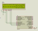
I have ported this mikroBasic code to mikroC code but the data displayed is not proper. What is the problem with the code ?

https://www.mikroe.com/forum/viewtopic.php?f=97&t=52891

The author of the mikroBasic code has shown that the data is displayed properly on hardware LCD. I am testing in Proteus as I have not yet received my 40x4 LCD. Is it a Proteus HD44780 40x4 LCD bug ? Can somebody test my code on hardware and reply if the text is displayed properly or not on the LCD ?

40x4 LCD 4 bit.png
 

Attachments

  • 40x4 LCD.rar
    79.2 KB · Views: 119

I added 30 ms delay but still doesn't work. First character in first line also doesn't display.

Here is another mikroBasic code. I will port this to mikroC code soon.

https://www.mikroe.com/forum/viewtopic.php?t=5602

Once I get the 4 bit parallel 40x4 LCD code working then I will use PCF8574 and make it 40x4 I2C LCD C code.
 

I added 30 ms delay but still doesn't work. First character in first line also doesn't display

According to step1 on link, it is recomended a minimal 100ms for initialization of HD44780 based LCD´s.
 
Ok. Changed the delay to 150 ms but still the same problem.
 

The circuit is not right, Vee should be connected to ground via a pot, and the unused inputs on the LCD should be left floating. The LCD inputs should be left floating as they have pull ups to the supply. This wont make any difference to Proteus, but is important when you come to build it up.
 
In Proteus pot is not needed. In hardware I have always grounded RW, D0-D4 pins of HD44780 cpmpatible LCDs and they have always worked fine.
 

@zuisti

I have used the same code. I also tried the code at libstock. Compiled for PIC18F45K22 by changing PORTx to LATx. Still the same problem. Maybe it is a bug of Proteus model.
 

Attachments

  • lcd40x4.png
    lcd40x4.png
    25.5 KB · Views: 94

Seems as you are using a code originaly designed to work with a 16x4 LCD.
 

HTML:
In Proteus pot is not needed. In hardware I have always grounded RW, D0-D4 pins of HD44780 cpmpatible LCDs and they have always worked fine.

If the R/W is grounded then it does not matter if you ground the D0-D4 pins. However there are pull up resistors on these pins so you will save a bit of current by leaving them floating.
 
I also tried the programs on the mikroE forum, and yes, seems they are wrong in LCD addressing and in E1-E2 handling (and ... very poor and inefficient coding, sorry).

After some Google-ing I found other solutions also:

https://www.ccsinfo.com/forum/viewtopic.php?t=32091

https://www.nerdkits.com/forum/thread/2023/

Attached the picture which shows the properties of the 40x4 LCD in Proteus 8. We can see the 2-3 line addresses are the same as the 1-2. I think in case of 1-2 have to use E1 (and for 2-3 lines the E2).

This is an interesting issue, later (when I have time) I used to try to handle the 40x4 LCD in mikroC.

But ... it is not at all certain that your actual LCD follows this (modifiable) model, the best to try it in reality ...
 

Attachments

  • 40x4_Pr8.gif
    40x4_Pr8.gif
    18.4 KB · Views: 100
@zuisti

Below is the code piece from nerdkits code.


Code C - [expand]
1
2
3
4
5
6
7
8
9
10
11
12
13
14
// lcd_write_nibble(...)
void lcd_write_nibble(char c) {
 
  // NOTE: only 2 or 3 work in the delays here.
 
  // set data
  PORTD &= ~(0x0f << 2);
  PORTD |= (c&0x0f) << 2;
 
  // Toggle E1 if in 1st two rows
  if(E1){PORTD |= (1<<PD6); delay_us(1); PORTD &= ~(1<<PD6); delay_us(1);}
  // Toggle E2 if in 2nd two rows
  if(E2){PORTB |= (1<<PB1); delay_us(1); PORTB &= ~(1<<PB1); delay_us(1);}
}


To toggle E1 or E2 pins how does he know whether data (nibble) is for first two rows or second two rows ?
 
As I see the nerdkits code always uses an lcd_goto_position function (or similar, like the lcd_home or the lcd_clear_and_home) to properly set E1 and E2, before EVERY char-out LCD functions, like the lcd_write_string, for example.

After examining the lcd_goto_position function we can see it uses other LCD addressing than on the above picture.
In Proteus use the LC4857 module (not the normal 40x4 module!), it works with the expected addressing, and works properly as the above ccsinfo site says at its last line.

Or ... simply modify the properties of the normal 40x4 LCD module.
 
Status
Not open for further replies.

Similar threads

Part and Inventory Search

Welcome to EDABoard.com

Sponsor

Back
Top