Continue to Site

Welcome to EDAboard.com

Welcome to our site! EDAboard.com is an international Electronics Discussion Forum focused on EDA software, circuits, schematics, books, theory, papers, asic, pld, 8051, DSP, Network, RF, Analog Design, PCB, Service Manuals... and a whole lot more! To participate you need to register. Registration is free. Click here to register now.

Performance of Oscillator

Status
Not open for further replies.

Englewood

Full Member level 3
Joined
Nov 2, 2014
Messages
178
Helped
0
Reputation
0
Reaction score
0
Trophy points
16
Activity points
1,294
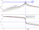
I have 3 outputs of a Wien Bridge Oscillator.

I need to compare the performance of each graph, each graph has been modified by a component.

1st graph with a 21k res
2nd with a 22k res
3rd with 2 diodes added.

I can see that when I have changed the resistor that the time base of the oscillator has decreased and the oscillation occurs earlier.

Adding two diodes to the circuit seem to clip the voltage to 6v

200ms Graph.jpg22k Resis Graph.jpgDiodes Graph.jpg
 

Yes - your graph`s show the expected behaviour. Any question?
For evaluation of the results you need to say where the mentioned resistor and the diodes are located.
 

The resistor is located at the inverting and at the output line and the 2 diodes are across the resistor
 

You can normally do a number of runs on most simulators by stepping a selected value between two limits. These results can then be overlay-ed for comparison. See example.
 

Attachments

  • gain_phase.png
    gain_phase.png
    41.8 KB · Views: 56

What I need to explain is the change in the graphs.

So a change in resistor has made the output voltage start to increase at a earlier time and gives a longer maximum output.

The two diodes have clipped the voltage to 6V (Why is this?)
 

The resistor is located at the inverting and at the output line and the 2 diodes are across the resistor

Yes - that`s what I have expected.
Nominal design: 20k (gain of 3)
Practical value: 21k or 22k (gain of 3.1 or 3.2).

In case of both practical values (necessary for a safe start-up of oscillations) the gain is larger than required by the classical Barkhausen condition.
As a consequence, the amplitude is rising until clipping occurs (voltage rail). This results in a bad signal form.
It is a normal and expected behaviour that the time for the amploitude to reach the final value is inversely proportional to the gain excess (3+0.1 or 3+0.2).
This is because the real part of the pole in the RHP is prop. to this gain excess.

Two anti-parallel diodes across this resistor provide amplitude-controlled "soft-limiting" to the gain of 3 with a rather good sinusoidal form (good THD).
 

A low distortion Wien Bridge oscillator has a thermistor (incandescent light bulb) or a Jfet in the negative feedback loop to provide an output level a little less than clipping level.
 

Cheers guys, very helpful once again. (Brainiacs :wink:).
 

Actually the Op Amps clip the sine wave from linear feedback in 1&2
In 3, the diodes increase the feedback and thus reduce the gain to soften the limiting and prevent clipping which is preferred.
 

Hello all of you,
I have observed that if I remove the parallel capacitor of the Wien Bridge Oscillator I have a nice astable mutivibrator.
All the best
ERIK
[email address deleted by moderator]
 
Last edited by a moderator:

Status
Not open for further replies.

Similar threads

Part and Inventory Search

Welcome to EDABoard.com

Sponsor

Back
Top