Continue to Site

Welcome to EDAboard.com

Welcome to our site! EDAboard.com is an international Electronics Discussion Forum focused on EDA software, circuits, schematics, books, theory, papers, asic, pld, 8051, DSP, Network, RF, Analog Design, PCB, Service Manuals... and a whole lot more! To participate you need to register. Registration is free. Click here to register now.

Differential amplifier issue in LM358

Status
Not open for further replies.

aramosfet

Junior Member level 2
Joined
Oct 21, 2005
Messages
22
Helped
1
Reputation
2
Reaction score
1
Trophy points
1,283
Location
Bangalore,India
Activity points
1,480
Hi All,

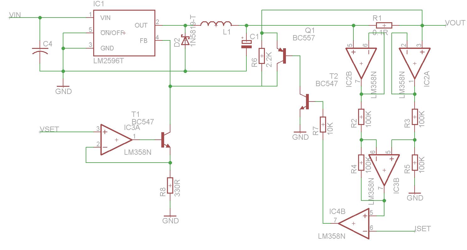
I'm trying to measure the current in a LM2576 power supply. I'm using a 1ohm current sense resistor on the output of the regulator. Using an LM358 opamp as differential amplifier, I see the output voltage is stuck at 0.6V when the differential amp resistors are 10K (instead of 18k in schematic). However when the resistor are changed to 100k, I get the correct differential voltage at the output. What is the reason for this?

Diif_amp.PNG

Thank you
 

Your problem of the output not going below 0.6V can be caused when the output must sink 12mA or more current to ground.
The inverting input of the differential amplifier must have a voltage that is the same as the voltage at the non-inverting input. Assuming that there is no output load current, when the 10k negative feedback resistor R18 has 12mA or more in it then it has a voltage from output to input of 120V which will blow up the opamp.

What is the load resistance of the opamp circuit?
 
The output load is nil, I have not connected anything other than a multimeter. It's not a question of output going below 0.6V. The output is stuck at ~0.6V irrespective of the input voltage difference. It only works when i tie the non inverting end of the differential input to ground. I see the same behavior in LM324. With some more experiments I see the below.
Vcc = 12V
Current through sense resistor varied between 10mA to 200mA, differential opamp output voltage varies from 0.580V to 0.61V.
I have measured the differential voltage between U12A output and R23 input (Sense resistor side) and it tracks 10mV to 200mV as expected.
Output at U12A voltage follower is correct.

With a 470ohm load on the differential amplifier output, I see that the output is able to go below ~0.5V but still about 50mV above the differential input voltage. So it appears to be a output sink capability problem.

From the datasheet, I see two sink current specifications, for V- = 1V, V+ = 0V , Vcc =15V
1) Vout = 2V , Sink current = 50mA
2) Vout = 200mV , Sink current = 50uA

Does that mean, as the output voltage goes down, the current sink capability also goes down?
 

You never said the voltages above 0V of the shunt. The inputs of an LM324 or LM358 opamp do not work when their voltage is within 1.5V of their supply voltage. So if their supply is +12V then keep the input voltages below +10.5V.
Their datasheets show a graph of the "typical" sinking capability. With a load current of 12mA or more, the output cannot go below 0.6V. With a load of almost nothing the output cannot go below 10mV.

Thanks for the reply.
So I continued the design and came up with the schematic attached. I need to have a small power supply with 2-30V, 0-2A. The required voltage and current limit will be set by a microcontroller through Vset and Iset pins. It is understood that in a case of overcurrent limit, the output voltage can only go down to ~1.23V and this is acceptable.

I designed the current sense and voltage set circuits based on several references on the web. Does this look ok?, Do I need to add some filtering for the current sense section?

Thank you.
 

Now you forgot to tell how the LM358 supply is connected.

I presume you are able to read and understand the LM358 common mode voltage specification and consider it your design.

By the way, omitting the superfluous buffer amplifiers T2A and T2B would about double the positive voltage range for the shunt and also reduce offset errors.

For the LM358 Supply, I plan to use a simple LM317 regulator at 32V. I hope 2V should be enough headroom. I understand the the buffers can be avoided since the differential amplifier input pulls relatively low current. Can you elaborate the doubling of the positive voltage range for the shunt? Do you mean to say that without input buffers, I can operate the LM358 at a lower supply for the same 30V at the shunt?
 

Yes, 2 V below Vcc would be sufficient margin for LM358 input voltage.
The simple point is that the shunt voltage is divided by 2 at the LM358 inputs, allowing a shunt voltage above the LM358 supply. You can even increase the voltage range by using a different resistor ratio, unfortunately increasing also the shunt related offset voltage. Alternatively you can give gain to the differential amplifier if the supply voltage is sufficient.

As a side remark, the current limiting/current control loop is not necessarily stable (unfortuantely load dependent) and may need additional frequency compensation.

Can you suggest how this compensation can be applied?

Thank you,
 

Not particularly. I wrote this comment without looking throroughly at your circuit. Now I realize that it has IC4b with open loop gain (connected as a comparator) and T2 as another gain stage. This topology actually inforces instability.

I would generally suggest a PI loop response, and cancel the extra gain built-in with your schematic. As a starting point


Shouldn't the diode be connected the other way round? The voltage on the FB pin needs to be pulled down if the current exceeds the set value.

- - - Updated - - -

Ignore the last post.. Wasn't thinking right.
 

Status
Not open for further replies.

Part and Inventory Search

Welcome to EDABoard.com

Sponsor

Back
Top