Continue to Site

Welcome to EDAboard.com

Welcome to our site! EDAboard.com is an international Electronics Discussion Forum focused on EDA software, circuits, schematics, books, theory, papers, asic, pld, 8051, DSP, Network, RF, Analog Design, PCB, Service Manuals... and a whole lot more! To participate you need to register. Registration is free. Click here to register now.

FM transmitter filter

Status
Not open for further replies.

mr_byte31

Full Member level 5
Joined
Oct 19, 2005
Messages
295
Helped
10
Reputation
20
Reaction score
8
Trophy points
1,298
Activity points
3,241
Hi All,

I checked some FM circuits over internet and all seems to miss the band pass filter at the last stage.
This make circuit transmits on all radio channel which is not something nice from my point of view

This circuit operates at 27 MHz and you can see the frequency domain and harmonics on the side of the middle peak
antenna_output_theory_.jpg


I was thinking about adding some filtration process before the antenna.

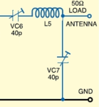
I only found a circuit that has filtration process at the end :
Capture.PNG

I would need to modify the L and C values so I can use it in the FM ranges (88-108 MHz)

would this idea work or i need more filteration stages?
 

Dear mr_byte31,

The circuit you posted in my opinion works as a impedance matching and as band pass filter too, however, it does not have a very good rejection to other frecuencies. I think you could try with a low pass filter. An easy filter to do which has good rejection for upper frecuencies is the Pi filter, it has only 3 passive parts (two variable capacitors and one coil) with a Pi filter you could have around of 20 to 26dB of rejection for 2nd and 3rd harmonic frequency.

I hope you can solve your question.
Have a nice day.

Best regards,

Juan
 
Last edited:
Hi Frank
The side peaks is due to the FM modulation , this is a common thing since FM follows Bessel functions.
REF : http://www.radio-electronics.com/in...y-modulation/spectrum-bandwidth-sidebands.php

My figure for the filter is from another circuit , i was just showing the connection :) sorry if this confuses you

- - - Updated - - -

Dear mr_byte31,

The circuit you posted in my opinion works as a impedance matching and as band pass filter too, however, it does not have a very good rejection to other frecuencies. I think you could try with a low pass filter. An easy filter to do which has good rejection for upper frecuencies is the Pi filter, it has only 3 passive parts (two variable capacitors and one coil) with a Pi filter you could have around of 20 to 26dB of rejection for 2nd and 3rd harmonic frequency.

I hope you can solve your question.
Have a nice day.

Best regards,

Juan

Hi Juan,

PI filter seems a nice option but it seems a LP :) , should I add another HP after it ?

pi_tiefpass_filter_01.jpg
 
Last edited:

Picture of Operational Amplifiers:
 

Attachments

  • Tensión_sinusoidal.JPG
    Tensión_sinusoidal.JPG
    35.7 KB · Views: 71

As your Fm modulation frequency is 4 MHZ, you need to maintain a wide flat bandwidth. I would just go for shunt series tuned circuits to short out harmonics of Fc ( X2,X3 ?).
Fraank

you mean something like that :
600px-Bandpass_Filter.svg.png
 

Status
Not open for further replies.

Similar threads

Part and Inventory Search

Welcome to EDABoard.com

Sponsor

Back
Top