kudjung
Member level 4
Dear All,
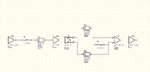
I'm learning to use Hyperlynx and trying to simulate a simple freeform schematic using SN65LVDS1/2, LVDS driver/receiver.
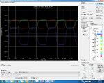
For some reason, common mode voltage of the LVDS output doesn't seem to be correct. Single end voltage at pin 3 and 4 is only around 400 mVolts instead of 1.2 Volts. Anyone know whether anything I did incorrectly in the schematic. I've attached the schematic and waveform of single-ende and differential output of U2 below.
Thanks in advance for any help.
I'm learning to use Hyperlynx and trying to simulate a simple freeform schematic using SN65LVDS1/2, LVDS driver/receiver.
For some reason, common mode voltage of the LVDS output doesn't seem to be correct. Single end voltage at pin 3 and 4 is only around 400 mVolts instead of 1.2 Volts. Anyone know whether anything I did incorrectly in the schematic. I've attached the schematic and waveform of single-ende and differential output of U2 below.
Thanks in advance for any help.