Continue to Site

Welcome to EDAboard.com

Welcome to our site! EDAboard.com is an international Electronics Discussion Forum focused on EDA software, circuits, schematics, books, theory, papers, asic, pld, 8051, DSP, Network, RF, Analog Design, PCB, Service Manuals... and a whole lot more! To participate you need to register. Registration is free. Click here to register now.

[SOLVED] Hall sensor as a normally closed switch

Status
Not open for further replies.

LinkZ

Newbie level 4
Joined
Jan 26, 2015
Messages
6
Helped
0
Reputation
0
Reaction score
0
Trophy points
1
Activity points
41
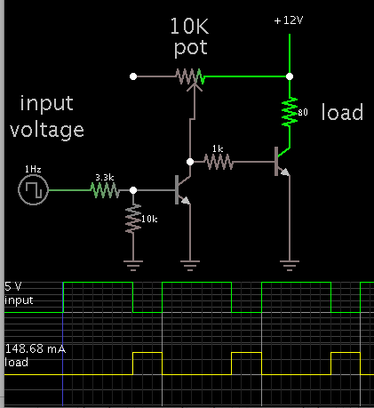
Hi, I need a normally closed switch which is opened when a magnet passes in front of the hall sensor. I found this schematic
hall-effect-switch.png
but as you can see this is a normally open switch. My question is: can I change Q1 with a NPN transistor to make this circuit work as a normally closed switch? And BTW my relay is this: https://www.futurlec.com/Relays/HORN12VDCSPSTpr.shtml.
 

hi,
The Hall device is open collector output, so you could use a NPN but it would mean changing other parts of the circuit.?
Do you follow OK.
E
 
Last edited:

I don't understand your question. I need that the hall OPENS the relay when a magnet passes in front of it, the circuit seems to CLOSE the relay when a magnet passes in front of it. Can I obtain the OPENING of the relay when the magnet passes in front of the hall sensor by just changing the Q1 with a NPN one? If not how can I do this? I only have a normally open relay that closes when energized. Can somebody help me? I posted this question in several forums but nobody helped me.
 

That circuit cannot work: the PNP transistor is reverse biased. You have to use a NPN transistor, instead (f.i. 2N1711).
When the hall sensor is in the vicinity of a magnet, its output it will be tied to ground so the NON transistor will open and the relais will be released. During normal operation the transitor will be closed, then the relay energized. Your relay need a 12 V, so you need to change the power supply voltage. I see the coil of your relay dissipates 1.6 W so a current of about 130 mA is required. You have to calculate R1 so that your transistor can supply such a current (with some margin).
 

Two NPN's can be arranged to shut off the load when the incoming bias signal goes positive.

Below is a simplified schematic.

The supply is 12V to power your relay (as stated in Albbg's post #4).

The control signal is 5V.


A single PNP would be able to do the job, if the control signal were 12V.
 

First of all thanks, for the replies. So according to albbg #4 with a NPN this circuit OPENS the relay when magnet faces the hall sensor, which is what i want. Can you please tell me how to properly calculate R1? Can I use 12V from a car to directly power the circuit, or i better use a zener to drop the voltage to 6V according to the schematics? Of course I need to change the relay and use a 5V one.
 

Can someone help me to calculate the R1 resistor?
 

Can I use 12V from a car to directly power the circuit

Yes it is able to power your circuit. This includes the 12V relay.

You will probably need to increase resistor values, so that no component gets overmuch current.

Can someone help me to calculate the R1 resistor?

Your project has several unknowns right now. It's difficult to make definite calculations.

It would help if you were to draw an updated schematic.
 

Hi LinkZ,

Please find the attached block diagram of Hall Sensor DN6848, its output is open collector and

I make it as normally closed switch.

- - - Updated - - -

The circuit you posted in your first post is not workable,

because PNP transistor is wrong connected, collector and

emitter should be interchange for proper working.
 

Attachments

  • Hall Sensor.PNG
    Hall Sensor.PNG
    39 KB · Views: 202

Hi LinkZ,

Please find the attached block diagram of Hall Sensor DN6848, its output is open collector and

I make it as normally closed switch.

- - - Updated - - -

The circuit you posted in your first post is not workable,

because PNP transistor is wrong connected, collector and

emitter should be interchange for proper working.

Thank you, so when the magnet faces the sensor the relay is off?
 

Status
Not open for further replies.

Similar threads

Part and Inventory Search

Welcome to EDABoard.com

Sponsor

Back
Top