Continue to Site

Welcome to EDAboard.com

Welcome to our site! EDAboard.com is an international Electronics Discussion Forum focused on EDA software, circuits, schematics, books, theory, papers, asic, pld, 8051, DSP, Network, RF, Analog Design, PCB, Service Manuals... and a whole lot more! To participate you need to register. Registration is free. Click here to register now.

Transformer circuit simulation with proteus

Status
Not open for further replies.

alamir2005

Newbie level 3
Joined
Jan 24, 2015
Messages
4
Helped
0
Reputation
0
Reaction score
0
Trophy points
1
Activity points
30
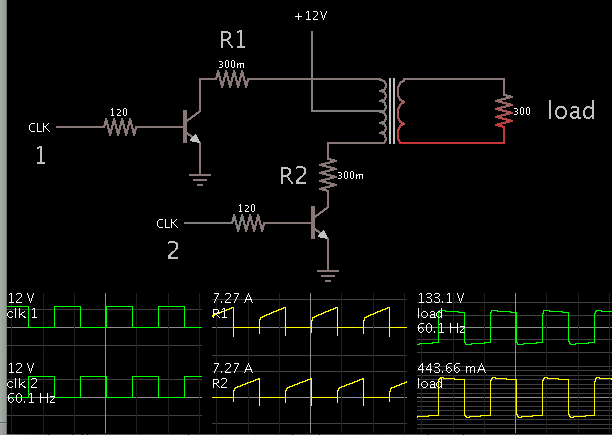
I have some issue with transformer in proteus and I don't find any answers here

i want to make the following
**broken link removed**
on proteus

the transformer here is center taped at primary , not at secondary
and I don't find any such transformer inside the proteus

so can I set that and what values I should use as inductance and coupling ?
 

Proteus has a center tapped transformer. Just flip secondary with primary side.

Refer to basic enginnering knowledge for relation betwen inductance and windings ratio, e.g. https://en.wikipedia.org/wiki/Transformer

and use a reasonable coupling factor like 0.95 for the start. Higher coupling is possible with special windings design.


thanks for the reply

you mean just making X mirror will make the center tap as output?
how X mirror will tell the proteus that this center belong the primary or secondary ?
this is the major problem

ya I know that it has center tapped but as secondary, not primary
if I flipped the transformer (x - mirror) what will tell the proteus which terminal are primary and which is secondary then ?
 
Last edited by a moderator:

Look at the model parameters, there's nothing specific for primary or secondary winding except windings ratio.
 

Are you somehow using all three terminals of the center-tapped primary at the same time?
If not then you just need a single primary winding for the simulation.
 

Are you somehow using all three terminals of the center-tapped primary at the same time?
If not then you just need a single primary winding for the simulation.

yes I use all of them
please see the image of the design here
**broken link removed**

as I need the cetner tap to apply 12V
 

In a different simulator I created the same inverter concept, and got it working.


The transformer has 2 adjustable specs: (a) primary inductance, and (b) turns ratio.

I used 3H, and .16. It is backwards as you can see. However it appears to work.

I think it is because dynamics in the secondary have an effect on the primary. Therefore the simulator works backwards, in a sense, to reach convergence.
 

A transformer model has no "direction". The coupling between windings is basically bidirectional. With a real transformer, the only significance of primary versus secondary is an add-on of 5 to 10 percent for the secondary winding to compensate for voltage drop at full load. When using a regular mains transformer "backwards" for a step-up converter, you need to consider this add-on.
 

In a different simulator I created the same inverter concept, and got it working.


The transformer has 2 adjustable specs: (a) primary inductance, and (b) turns ratio.

I used 3H, and .16. It is backwards as you can see. However it appears to work.

I think it is because dynamics in the secondary have an effect on the primary. Therefore the simulator works backwards, in a sense, to reach convergence.

sorry but I think this circuit should provide sine wave at the end , not the wave you output
am I right ?

A transformer model has no "direction". The coupling between windings is basically bidirectional. With a real transformer, the only significance of primary versus secondary is an add-on of 5 to 10 percent for the secondary winding to compensate for voltage drop at full load. When using a regular mains transformer "backwards" for a step-up converter, you need to consider this add-on.

ahaa ok , thanks much for this point
 

Status
Not open for further replies.

Similar threads

Part and Inventory Search

Welcome to EDABoard.com

Sponsor

Back
Top