Continue to Site

Welcome to EDAboard.com

Welcome to our site! EDAboard.com is an international Electronics Discussion Forum focused on EDA software, circuits, schematics, books, theory, papers, asic, pld, 8051, DSP, Network, RF, Analog Design, PCB, Service Manuals... and a whole lot more! To participate you need to register. Registration is free. Click here to register now.

[SOLVED] AC circuit Working on breadboard but not on PCB

Status
Not open for further replies.

nitinjndal

Newbie level 5
Joined
Jun 23, 2008
Messages
9
Helped
0
Reputation
0
Reaction score
0
Trophy points
1,281
Activity points
1,346
Hi,

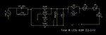
I am working on LED bulb. I have made circuit . I have series connection of 16 3.2V LED, and a 1K 1W resistor. But the circuit that is on bread board is working fine but with the same circuit on PCB the resistor is getting very hot. Can anybody tell what can be the problem. Mains supply is 220V.

Thanks,
Nitin
 

Show us the circuit. From my assumption...check the voltage drop of the 1K resistor, i believe the input voltage is too high even with 16 diodes in series which heating up the resistor. By the way, are you directly rectifying the main supply on your board? be extra careful if you are.
 

Hi,

I have attached the circuit.
 

Attachments

  • LED_BULB.jpg
    LED_BULB.jpg
    35.7 KB · Views: 129

You stated it has a 1K resistor in series but the circuit shows 280 ohms.

are there other differences?
 

Also note that the reactance of the '155K' capacitor, assuming you have 50Hz AC is only about 2.1K so if the dotted line is a switch and you open it, the voltage across the 100uF capacitor will try to go as high as about 300V. I doubt it would reach it without letting you know in a surprising way.

Brian.
 

Hi,

Thanks for such a quick response.

There is no other difference in the circuit. Actually I have used both 1K and 280 ohm resistor , both are getting too hot.

Brian, the dotted line is to show that LED's are repeating i.e. there are 13 more LED's.


Thanks,
Nitin
 

With the schematic as shown, the two series resistor dissipate approximately 1.35W between them so you should be using at least 1W resistors in each position. Without knowing what kind of resistors and the method of construction it's difficult to predict how hot they should be running. The only way to reduce the heat is to reduce the current and the simplest electrical method of doing that is to reduce the value of the 1.5uF capacitor. Your total series resistance is about 2.4K , if you can reduce the capacitor to 1.4uF and change the resistors to 270 Ohms it should run much cooler.

Brian.
 

Hi,

Thanks for the suggestions. I found it out that the value of resistor I am using is much higher. Now I am using 28ohm 0.25W resistor instead of 280ohms and it is running cool. But I am still not clear why it is working on bread board.

Yes Brian, You are absolutely right that both resistors are consuming about 2.7W power. So to reduce the power, I have to reduce current and for that either I have to reduce the resistance or the series capacitance. But since I need same amount of current for LED's I should not change the value of capacitor. thats why I have reduced the resistor value.

Please let me know if my understanding is incorrect.

Thanks a lot.
 

Not quite. The current is decided by the combined reactance (XC) of the capacitor and the resistors added together. If you increase the capacitor value you decrease XC and the current increases. Similarly, if you increase R the current decreases. The opposite happens if you change the values the other way. You share the voltage drop between XC and R so by just dropping R you have increased the LED current. You could remove R altogther if you had the exact value of C and you could remove C if you had the exact value of R. the reason C is used is it has almost no power loss while R has a large power loss.

For example, if you removed C and relied purely on R, the value would be 2.4K but it would dissipate almost 12W of heat, over three times more power than the LEDs consume!

Brian.
 

Ok Understood. Thanks for the help. the circuit is working fine.
 

Status
Not open for further replies.

Part and Inventory Search

Welcome to EDABoard.com

Sponsor

Back
Top