Continue to Site

Welcome to EDAboard.com

Welcome to our site! EDAboard.com is an international Electronics Discussion Forum focused on EDA software, circuits, schematics, books, theory, papers, asic, pld, 8051, DSP, Network, RF, Analog Design, PCB, Service Manuals... and a whole lot more! To participate you need to register. Registration is free. Click here to register now.

FPGA Design, Digital Clock

Status
Not open for further replies.

action taker

Newbie level 4
Joined
Jan 23, 2015
Messages
7
Helped
0
Reputation
0
Reaction score
0
Trophy points
1
Activity points
49
Hello,
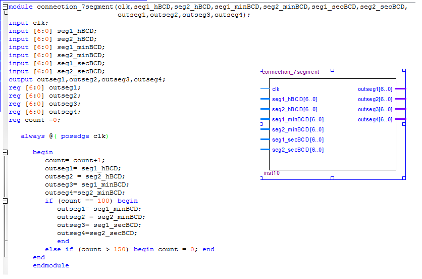
I've built a digital clock using QuartusII. it shows hours, minutes and seconds. teh testbench works fine. i want to implement the design on an FPGA, Cyclon III. the problem is, the FPGA has four 7 segments, how can i show the seconds?!. i tried to add a delay counter to show the seconds after a specified period, but i cant connect it to any of the four 7 segments, it says that the pins are already assigned. any ideas?!

thanks in advance.
 

Multiplex the seven seg outputs hh:mm and - -:ss, the you connect the multiplexer's output to the seven seg display.
 
If I am not wrong the FPGA, Cyclon III has 4 user push button switches. You can use any two of them. Modify your design in such a way that if one of the buttons are pressed the display is HH:MM and then if the other is pressed the display is MM:SS.
I would have done it this way. Ignore this post if there are no push-button switches on the FPGA board.
 
thanks for your replay ads-ee,
i built three counters hours,minutes and seconds and for each counter i've connected a BCD. each BCD has two output signal like the following hh:mm:ss. so do i or the two BCD signals then connect it to the MUX?!

- - - Updated - - -

it has three push buttons and i've used them to reset the hours, minutes and seconds. i thought of doing that and tried to implement it but i dont know how to connect the push button to the seven segment or is it connected automatically?! i searched alot but found nth, even in the DE0 user manual they didnt mention anything about that :(
 

but i dont know how to connect the push button to the seven segment or is it connected automatically?
You are not looking for a hardware feature of the DE0 board, you are exclusively talking about functions that have to be created in your VHDL or Verilog (or may be schematic) hardware description.

There are also switches on the DE0 board, so you should find a way to make the intended input. You could also make the display changing periodically without user interaction.

Your question suggests that you managed to run a design example on your board, but don't actually understand how it works.
 
it has three push buttons and i've used them to reset the hours, minutes and seconds. i thought of doing that and tried to implement it but i dont know how to connect the push button to the seven segment or is it connected automatically?

The push button sw are never connected to the displays. Connect the sw as an input to your design. The FPGA design manual has info how to the map the push button sw to an i/p pin of the FPGA and use it as an input port in your design.

Then slightly modify your design such that when the sw is asserted, the display data format is changed. E.g. If after dwnld your bit-stream the display shows MM:SS, then after pressing the push button sw, the display will be changed to HH:MM.

Take a note of as suggested by FvM: "You could also make the display changing periodically without user interaction." if you don't want to use the push button switches.
 
Last edited:
You are not looking for a hardware feature of the DE0 board, you are exclusively talking about functions that have to be created in your VHDL or Verilog (or may be schematic) hardware description.

There are also switches on the DE0 board, so you should find a way to make the intended input. You could also make the display changing periodically without user interaction.

Your question suggests that you managed to run a design example on your board, but don't actually understand how it works.


i am trying to display it periodically, that is why i have added a delay counter that counts for 4 seconds before displaying the seconds but my problem is i dont know how to connect the ss output to the 7 segments. the other 7 segments are connected to the hh:mm . how can i connect the ss to them? how can this be done?

thanks in advance
 

ads-ee gave the answer in post #2, use a multiplexer.

ok, i have thought about this even before i post, but since i have three BCDs and each one has two output signals, that means i'll have six inputs to the multiplexer, right? can i create a multiplexer with four outputs?! and each output will be connected to a 7 segment, if this can be done then isn't this against the definition of the multiplexer!
 

i built three counters hours,minutes and seconds and for each counter i've connected a BCD. each BCD has two output signal like the following hh:mm:ss. so do i or the two BCD signals then connect it to the MUX?!

The multiplexer switches which BCD values are output onto the seven seg. driver bus. Schematically it looks like this:
Capture.JPG

What you use to drive the select determines how the display switches, either use a timer and flip all the select lines to hh:mm or --:ss (-- is either off or maybe even just the center segments) or you could use your switch to select the :ss display.
 
The multiplexer switches which BCD values are output onto the seven seg. driver bus. Schematically it looks like this:
View attachment 113494

What you use to drive the select determines how the display switches, either use a timer and flip all the select lines to hh:mm or --:ss (-- is either off or maybe even just the center segments) or you could use your switch to select the :ss display.

that looks interesting. i've wrote this code shown in the image


basiclly what i've done is, i took all the signals from the BCDs s inputs and i used if statements to decide which signals to display and assigned them to the output, the output would be hh:mm, then if the counter is 100 i changed the outputs so it would be mm:ss and when the counter is greater 150 it will reset to 0. so the secounds should appear for 50 clk cycles. i suppose i need to work on the timing more but is this legal? does it make sense?!
 

Actually you want to check for count >= 100 && count <= 150, otherwise you'll only update the min/sec display for a single clock cycle which will freeze the output until the next time it gets captured (if you want to display seconds counting then you don't want to freeze the count. What you've done in your code is make a multiplexer with a select that is derived from a count value.

Also you should use non-blocking assignments (<=) in edge sensitive always blocks. Using blocking assignments (=) can lead to simulation/synthesis mismatches. You should only use the blocking assignments in combinational always blocks i.e. always @*.
 
great. thanks for your time and help.

regards
 

Status
Not open for further replies.

Similar threads

Part and Inventory Search

Welcome to EDABoard.com

Sponsor

Back
Top