Continue to Site

Welcome to EDAboard.com

Welcome to our site! EDAboard.com is an international Electronics Discussion Forum focused on EDA software, circuits, schematics, books, theory, papers, asic, pld, 8051, DSP, Network, RF, Analog Design, PCB, Service Manuals... and a whole lot more! To participate you need to register. Registration is free. Click here to register now.

How to read Tx signal from RS232 side

Status
Not open for further replies.

cool.man

Full Member level 6
Joined
May 29, 2008
Messages
323
Helped
42
Reputation
84
Reaction score
29
Trophy points
1,308
Location
Earth
Activity points
3,307
Hi everyone
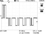
I want to know how i read this data which is transmitted from RS232 (PC side) of the following side.
F0008TEK.JPG

Settings are:
Baud Rate = 9600
No of data bits = 8
Parity = None
Stop bit = 1

Normally there are two states, logic 0 (3v to 25v) and logic1 (-3v to -25v).
But in the above diagram there is another state which is appox at -3v. So how should i read the data bits?
 

All you are seeing is an imbalance between the positive and negative voltages, if you are using AC coupling to your oscilloscope, use DC instead or adjust the center line to be zero on your screen.

A difference between positive and negative levels is not a problem unless it is so high that is upsets the receiver and it can't 'see' the opposite polarity. In the majority of RS232 receivers, the negative voltage is actually ignored and only the positive voltage above ground matters. The negative voltage is a legacy from the days when RS232 was used to drive mechanical teletype machines.

Brian.
 

The waveform doesn't look like a regular RS232 signal. A standard RS232 receiver would ignore the negative going pulses and see everything below 0.5-1 V as low (mark) state.

Have you two signals shorted (e.g. TxD and a handshake signal)?
 

Thanks for the replies.
The signal is coming form the PC RS232 and going into a module.There are only three pins connected (TX RX and GND). There is no handshaking signal.
Also on the oscilloscope DC coupling is selected and center line is at zero.

Also in the module which is communicating to PC, there is no max232 IC but have discrete components for transmitting and receiving.Maybe i am seeing signal because of this circuit. Is it possible?
 
Last edited:

That doesn't make sense, either you have a faulty PC serial port or you are measuring across the wrong points. As FvM pointed out (and overlooked by myself), the polarity should swing positive to negative with each bit transition but you are seeing a group of pulses with the same positive polarity followed by a group with negative polarity.

You might get these symptoms if you cross the ground signal with either TXD or RXD but as it originates in the PC I doubt it is caused by your discrete component interface. Can you post the schematic of the interface you are using please.

Brian.
 

I don't have it schematics because i purchased the module form a company. When i connect module with PC using Serial cable it communicates without any error and displays the readings on PC.
What i wanna do is to read those parameters from module in micro-controller and perform different functions.
For this purpose i am looking for the Tx and Rx signal and then i will send same data stream form micro-controller and receive the data.
The serial cable they provided have only three connections Tx,Rx and Gnd and i am seeing the wavefrom across the Tx with respect to Gnd.

ok.i found something.when i connect my probe's ground with the serial port GND, the same response i get as shown in fig.but when i connect the probe's ground with the module GND it shows the correct waveform as it suppose to be.
Then i check if the both gnd are common or not.Both the grounds are common.i checked it using multimeter.
Why this behaviour?
 
Last edited:

Does not compute.......

You are saying that moving your scope probe from the serial port GND to the module GND makes the fault go away but both GND points are linked together. At very high frequencies I might expect some difference but at low speed serial rates the signals should be almost identical. When you measured with your multimeter, did you have the scope probe ground connected at the same time. I'm thinking perhaps the 'common' (= linked) GND points are really isolated and you were measuring them as linked through the scope wires.

Brian.
 

The 2 GNDs should be connected to each other, if you want any data to be transferred. Even if not connected you can't get a valid measurement if you don't connect the probe to the GND for the connector you measure the TX signal on.

GND is not an universal level, just a name refering the local 0V potential. If you want 2 units to have the same GND, you always need to connect them, preferably in just one point.
 

Gorgon, my understanding from post #7 is the GND at both sides are already connected. That makes no sense with regard to a different signal being seen depending on which of them is used as the scope ground. I suspect the 'common' being measured with cool.man's multimeter is actually a connection from one real ground (probably the PC end) and the module ground but through the scope cable rather than a direct wired connection. There certainly should be a permanent direct wired connection between PC and module GND pins.

Brian.
 

Status
Not open for further replies.

Similar threads

Part and Inventory Search

Welcome to EDABoard.com

Sponsor

Back
Top