Continue to Site

Welcome to EDAboard.com

Welcome to our site! EDAboard.com is an international Electronics Discussion Forum focused on EDA software, circuits, schematics, books, theory, papers, asic, pld, 8051, DSP, Network, RF, Analog Design, PCB, Service Manuals... and a whole lot more! To participate you need to register. Registration is free. Click here to register now.

Differential Pair Negative Feedback for audio amp

Status
Not open for further replies.

pha0001m

Junior Member level 1
Joined
Jan 10, 2015
Messages
16
Helped
1
Reputation
2
Reaction score
1
Trophy points
3
Activity points
138
Hi all, I am currently working on a phase splitter for my valve audio amplifier. However, I wanted to design the phase splitter stage with transistors instead of traditional valves.

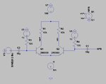
The original circuit, which was implemented with vacumm tubes is attached in figure 1. My LTspice attemped is attached in figure 2. The attempted failed, does anyone has any idea on how to implement a BJT phase splitter.

Thanks,
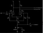
figure 1.jpgNFB.jpg
 

You didn't tell in which sense the circuit fails. I guess it's because you erroneously implemented positive instead of negative feedback.

Did you omit the feedback signal attenuation of the original circuit intentionally?
 

R3 and R4 in your simulator figure are too low. I can not see why a long tailed pair would not work, there are problems with
impedance matching to the existing circuits and I wonder if the Miller affect could be problematic.
Frank
 

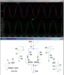
Below is my simulation of your circuit, which looks okay to me.
What is the problem with yours?
The feedback phase is confusing because you labeled the inverted signal as + and the non-inverted as -.

Why are R3 and R4 such a low value?

Phase Splitter.gif
 

R3 and R4 in your simulator figure are too low. I can not see why a long tailed pair would not work, there are problems with
impedance matching to the existing circuits and I wonder if the Miller affect could be problematic.
Frank

Below is my simulation of your circuit, which looks okay to me.
What is the problem with yours?
The feedback phase is confusing because you labeled the inverted signal as + and the non-inverted as -.

Why are R3 and R4 such a low value?

View attachment 113287

Thank guys! and thanks for the verification, crutschow! You are right I got mix up with the + and -. Thus I was doing a positive feedback instead of a negative feedback.

R3 and R4 are indeed too low, and they will be increased. I was not thinking properly when I selected these values.

- - - Updated - - -

You didn't tell in which sense the circuit fails. I guess it's because you erroneously implemented positive instead of negative feedback.

Thanks, and yes, you are right! My bad, I was doing a positive feedback, no wonder it was giving me some odd looking results.


Did you omit the feedback signal attenuation of the original circuit intentionally?

Do you mean the feedback connected below R6 in the original schematic?. I omitted it because I am not sure how to included it when the tail resistors are replaced by a constant current sink.
 

Do you mean the feedback connected below R6 in the original schematic?
Either if it's connected to R6 or elsewhere, there's a voltage divider with 1:20 or even larger voltage reduction.

As a special point, the feedback is also frequency dependant, optionally achieving medium and high frequency ("Presence") enhancement. I would ignore this feature at first sight.
 

The "presence" control on the original old amplifier boosted midrange frequencies that caused the output to sound like a telephone with reduced bass and reduced highs.
 

Very curious. The circuit simulation works for either polarity of the NFB signal (as my previous post shows for positive feedback). The only difference is that the polarity of the differential output signal also reverses, even though it's amplitude is essentially unchanged.

After some testing it turns out that the simulator finds a quasi-stable state where the circuit will operate with a value of 0.1 positive feedback. If you Skip the initial operating point solution (UIC) then the circuit oscillates as expected. It works properly with negative feedback.

An interesting case where the simulator gives a result that would be difficult (if not impossible) to achieve in the real world. So always beware if the simulator is giving a result that appears incorrect.
 
Last edited:

Status
Not open for further replies.

Similar threads

Part and Inventory Search

Welcome to EDABoard.com

Sponsor

Back
Top