Continue to Site

Welcome to EDAboard.com

Welcome to our site! EDAboard.com is an international Electronics Discussion Forum focused on EDA software, circuits, schematics, books, theory, papers, asic, pld, 8051, DSP, Network, RF, Analog Design, PCB, Service Manuals... and a whole lot more! To participate you need to register. Registration is free. Click here to register now.

[Moved]: RF electric field penetrating glass tube

Status
Not open for further replies.

toyonline

Member level 2
Joined
Jan 17, 2014
Messages
46
Helped
0
Reputation
0
Reaction score
0
Trophy points
6
Activity points
457
Hi, I am designing a RF electric field inside a glass tube. I have some questions not quite sure.

The glass tube is of 200mm long and 10mm diameter. The RF electric field is perpendicular to the glass tube, and is applied through a parallel of metal plates. I would like to use electric field inside the glass tube for special application purpose. The RF is 300Vpp @ 1MHz.

My questions are:

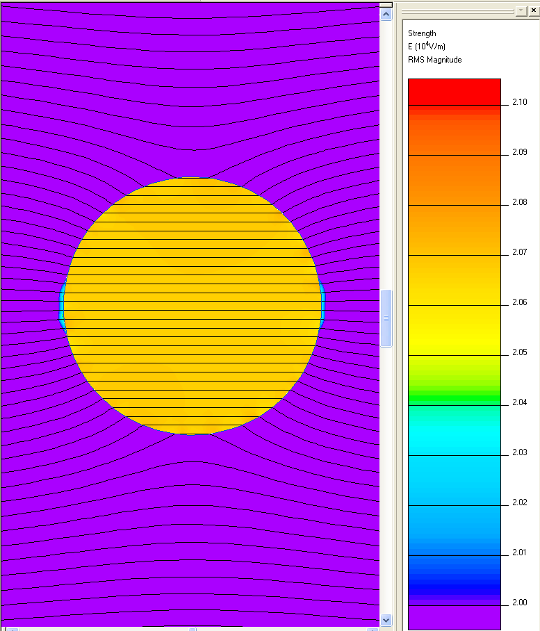
1) whether the glass tube will induce some kind of shielding to the applied alternating electric field inside the tube? any measurable changes inside the electric field?

2) the field direction between two parallel plates should be parallel (in other words, field strength should be all the same). What would happen to the electric field direction inside that glass tube?

To my knowledge, glass is a good insulator so that it will not impose any shielding inside, under external electric field. But I am not sure whether this is true in practical aspect?

Thank you.

--Toyonline
 

Re: RF electric field penetrating glass tube

According to low frequency, the problem can be analyzed as AC electrostatic problem.

A parallel field will be distorted by any dielectric material, this is also the case for a glass tube. For this reason, the field inside and around the tube isn't exactly parallel.

Of course any dielectric or conductive substance inside the tube will further modify the field.

For a simulation/calculation of the field pattern, the wall thickness matters.
 

Re: RF electric field penetrating glass tube

Thanks FvM.

For the glass tube, the outer diameter is ~10mm, and the inner diameter is ~0.5mm. So the thickness is ~5mm.

RF I used is at ~1MHz.

I have no idea whether this frequency is high or low for considering modifying effect caused by glass tube.

Under those conditions, i.e. thickness and frequency, will there be significant difference change for the field inside the tube? Any suggestions to do simulation or a estimation?

Thanks.

--Toyonline

According to low frequency, the problem can be analyzed as AC electrostatic problem.

A parallel field will be distorted by any dielectric material, this is also the case for a glass tube. For this reason, the field inside and around the tube isn't exactly parallel.

Of course any dielectric or conductive substance inside the tube will further modify the field.

For a simulation/calculation of the field pattern, the wall thickness matters.
 

Re: RF electric field penetrating glass tube

That's rather a glass cylinder than a tube.

What's the distance between glass and electrodes?

- - - Updated - - -

Different glasses have different Er, between 4 and about 6.5
 

Re: RF electric field penetrating glass tube

Exactly, it's a glass cylinder. And the working area is hollow area within (full of air). So the glass acts as a barrel.

The parallel electrodes outside are separated by ~10mm.


That's rather a glass cylinder than a tube.

What's the distance between glass and electrodes?

- - - Updated - - -

Different glasses have different Er, between 4 and about 6.5
 

Why can't you use the electrodes inside of glass tube? Then the E field between them is not affected`by glass. Look on historical CRTs used in oscilloscopes for electron beam drive.
 

The parallel electrodes outside are separated by ~10mm.
Means they are effectively touching the glass.

In tis case the field strength in the bore will be slightly higher (e.g. 25 %) than the undistorted free field.

 
Distance between electrodes are slightly larger than outer diameter of the glass (~0.5mm).

From your simulation, I see a nearly uniform electric field in that central hole region, which is actually the useful region in my application. Since the region is so small (i.d. ~0.5mm), the distortion in electric field is essentially insignificant.

On the other hand, I do not understand your statement of slightly higher field inside. Since the dipole of glass imposed by electrodes will produce additional inside electric field at opposite direction, I think the total field strength inside the glass tube will be somehow reduced (incomplete shielding effect of the dielectric). Am I right?

Your simulation is intuitive and cool. How did you make that? Using comsol?

Thank you.

Means they are effectively touching the glass.

In tis case the field strength in the bore will be slightly higher (e.g. 25 %) than the undistorted free field.

- - - Updated - - -

Fabrication of electrodes inside a small glass tube is not easy for me, especially when I need the distance adjustable electrodes. Also I need the inside area sealed from outside.

I have tried to think about fabricating some rectangular hole inside some special material, and let the inside tube surface coated with Au. Somehow like making PCB board. But I didn't find a way to coating just opposite surfaces and let the other two faces uncoated.

Do you have good suggestions?

Why can't you use the electrodes inside of glass tube? Then the E field between them is not affected`by glass. Look on historical CRTs used in oscilloscopes for electron beam drive.
 

On the other hand, I do not understand your statement of slightly higher field inside. Since the dipole of glass imposed by electrodes will produce additional inside electric field at opposite direction, I think the total field strength inside the glass tube will be somehow reduced (incomplete shielding effect of the dielectric).

There's in fact a shielding effect. But it's compensated or even overcompensated by bringing the electrodes near to the glass. With 0.5 mm distance, the in-bore fieldstrength is still slightly higher (7%) than the undistorted field strength without dielectricum. The effect is cancelled with further increasing the electrode to glass distance.

On the other hand, you get higher field strength by attaching quarter arc electrodes directly to the glass (about doubled).

The field picture was generated with QuickField Student Edition.
 

Thanks so much.

So the in-bore field strength is overcompensated and slightly higher. I wonder how much will the field direction be distorted in the in-bore region? since I see less information in the in-bore region in your attached picture. Would you show me the field in-bore with slightly higher resolution?

I have downloaded a student version QuickField, and am learning how to use it. Thanks so much for you.

--Toyonline

There's in fact a shielding effect. But it's compensated or even overcompensated by bringing the electrodes near to the glass. With 0.5 mm distance, the in-bore fieldstrength is still slightly higher (7%) than the undistorted field strength without dielectricum. The effect is cancelled with further increasing the electrode to glass distance.

On the other hand, you get higher field strength by attaching quarter arc electrodes directly to the glass (about doubled).

The field picture was generated with QuickField Student Edition.
 

Electric field penetrating glass tube

Hi, as discussed in previous thread, I want to create electric field inside a glass bore.

Previous thread:
https://www.edaboard.com/threads/330196/#post1409914

Through simulations, I have seen possibility of E field inside a glass bore. But then comes my experiment. I see no electric field effect inside the bore.

Briefly, the expt. was as follow:

Using a beam of positively charged ions to travel through the bore. Since the ions were positively charged, they are sensitive to E field. If the E field create a potential difference perpendicular to ion travel direction, they will alter the travel trajectory and will not be detected after the glass bore, with a Faraday cup.

However, I don't see any difference with and without E field perpendicular to the glass bore.

Would anyone have interests and give some suggestions? Since I don't understand the expt. outcomes and simulation results.


--Toyonline
 

I would expect some calculations first:
- ion energy, mass and respective speed
- length of acceleration zone and time of flight
- expected deflection
 

Glass has a permittivity of around 4 , the same as paper and circuit board material. Being a good insulator, it will not affect the conducted field at 1MHz however charges may accumulate on contaminated air or surfaces which may result in a partial discharge in a tiny gap < 300Vpp, so keep it clean.

Light weight gasses may also reduce the dielectric breakdown voltage in the chamber relative to air, but glass has a higher breakdown voltage than air.

There should be no problems penetrating a glass tube but if you want a low voltage breakdown for ionizing the gasses then you will put in high power RF , with an inert gas heating up the contaminant gas stream and end up with a gas chromatography with >100W of RF power.
 

Yes, I have done a preliminary estimation of expected deflection.

A high speed gas flow drives ions to travel through the glass bore. The speed of ions were several hundreds m/s. Traveling through the outside E-field region typically last for several milliseconds. Although the traveling speed is fast, a higher electric potential difference still could bent ion trajectory to collide with inner faces of the glass. If this was the case, a significant current drop will be observed at the other end, where a Faraday cup was placed. But in my expt., no obvious current drop was observed, whatever E potential I applied to the outside electrodes.


I would expect some calculations first:
- ion energy, mass and respective speed
- length of acceleration zone and time of flight
- expected deflection

- - - Updated - - -

Initial ions were not generated by RF breakdown of gases. Actually it was generated outside the tube, and a negative vacuum pressure drags ions inside through the bore.

Glass has a permittivity of around 4 , the same as paper and circuit board material. Being a good insulator, it will not affect the conducted field at 1MHz however charges may accumulate on contaminated air or surfaces which may result in a partial discharge in a tiny gap < 300Vpp, so keep it clean.

Light weight gasses may also reduce the dielectric breakdown voltage in the chamber relative to air, but glass has a higher breakdown voltage than air.

There should be no problems penetrating a glass tube but if you want a low voltage breakdown for ionizing the gasses then you will put in high power RF , with an inert gas heating up the contaminant gas stream and end up with a gas chromatography with >100W of RF power.
 

You have been initially talking about 1 MHz RF field, now it seems that you are applying DC. But a DC field inside the glass tube will be immediately neutralized by trapped ions.
 

Both RF and DC will be used. I need to investigate DC behavior at the first step.

Ions will be deflected to inner wall of the glass bore, and then there will be excessive charge density inside the bore.

According to ion current observed (~100pA) and surface area of glass bore (~300 mm^2), charge density inside was estimated to be in 10^-7 C/m^2 range in several seconds time.

I have used above condition and redo the simulation by QuickField, and see redistributed field as attached. It seems to me, the field potential gradient still exist and will lead to a decrease of ion current at the exit.

There must be something wrong in my reasoning.


You have been initially talking about 1 MHz RF field, now it seems that you are applying DC. But a DC field inside the glass tube will be immediately neutralized by trapped ions.
 

Attachments

  • E field glass bore.PNG
    E field glass bore.PNG
    27.3 KB · Views: 51

You are probably right that the field distribution will survive at least several seconds before it's neutralized by the accumulated ions. In so far you should be able to apply field if you switch the polarity now and then.

Is it atmospheric pressure? In a first order, the ions are carried by the gas stream. Lateral drift according to electrical field is only a minor effect.
 

Electric field will continue to distort and redistributed according to accumulated ions, and will eventually be at electric equilibrium, which is somehow similar to total electric shielding inside a metal bore. Is the analysis reasonable?
You are probably right that the field distribution will survive at least several seconds before it's neutralized by the accumulated ions. In so far you should be able to apply field if you switch the polarity now and then.

- - - Updated - - -

The major driving force for ions traveling along the bore is air drift. Two ends of the glass tube are in atmospheric pressure and low vacuum, respectively. The gas drift speed is therefore a litter bit higher (~1000m/s).

But even at this kind of speed boundary condition, a sufficient large lateral electric field still could bent ion trajectory according to dynamics law.

Is it atmospheric pressure? In a first order, the ions are carried by the gas stream. Lateral drift according to electrical field is only a minor effect.
 

Status
Not open for further replies.

Similar threads

Part and Inventory Search

Welcome to EDABoard.com

Sponsor

Back
Top