user92
Newbie level 3
Hi all,
I have been stuck on this for a while and would be grateful if anyone can give some help.
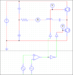
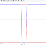
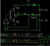
I am modeling a half bridge resonant inverter in PSIM and my issue is with the Bi-polar PWM control. I can not figure out how to introduce a dead time between two switches operating.
Anyone have any pointers? I see there is other two PWM blocks but I am finding it difficult to get it to work correctly. I looked at the examples and they are full bridge so its somewhat different.
Thanks


