Continue to Site

Welcome to EDAboard.com

Welcome to our site! EDAboard.com is an international Electronics Discussion Forum focused on EDA software, circuits, schematics, books, theory, papers, asic, pld, 8051, DSP, Network, RF, Analog Design, PCB, Service Manuals... and a whole lot more! To participate you need to register. Registration is free. Click here to register now.

pwm to control proportional valve

Status
Not open for further replies.

mshh

Full Member level 6
Joined
May 30, 2010
Messages
349
Helped
0
Reputation
0
Reaction score
0
Trophy points
1,296
Location
usa
Activity points
3,871
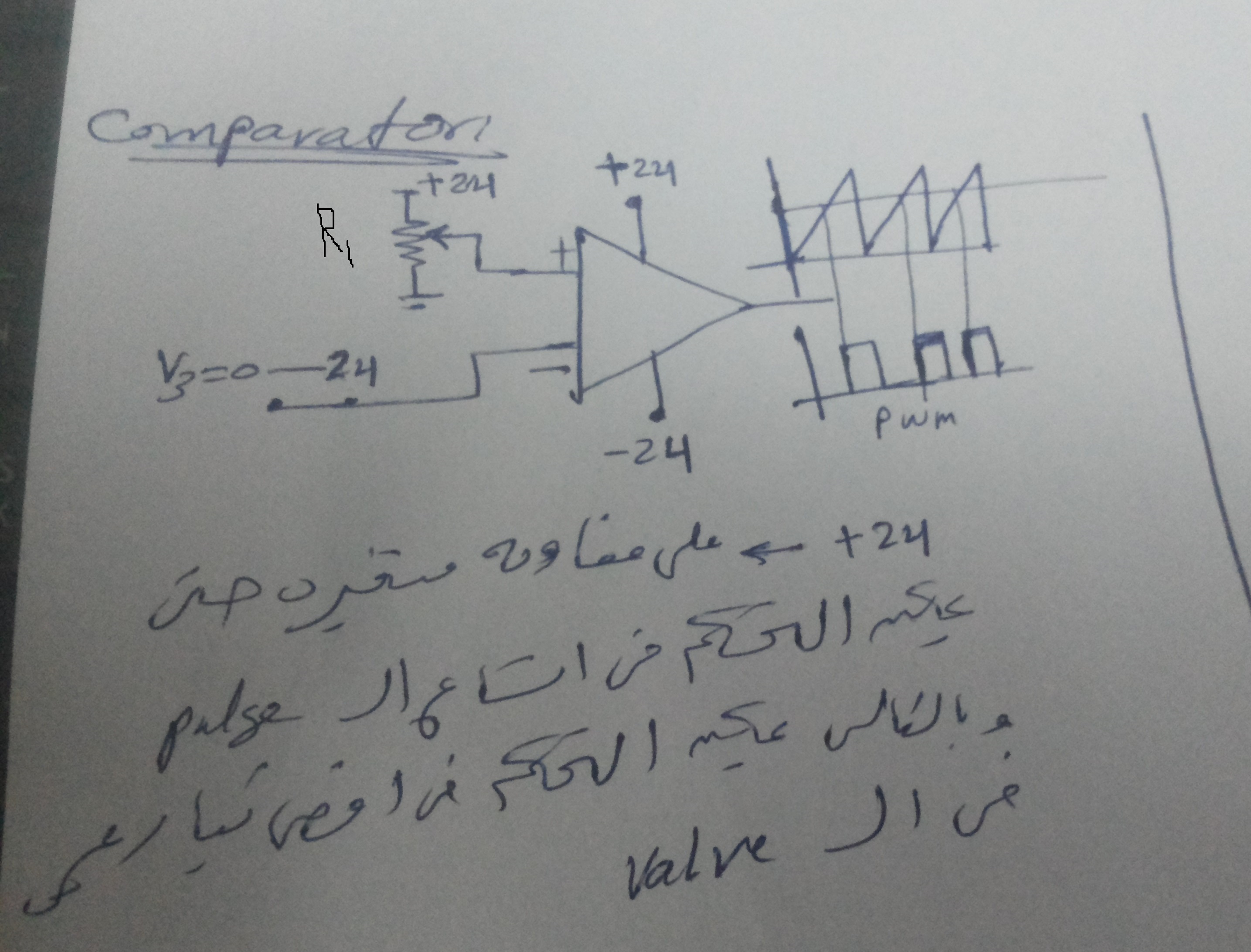
i want to drive proportional valve from a plc .the valve specs is 24V 1.5Amp. the output from plc is 0-10V , i will amplify it to 0-24 v . now the problem in driving phase . if i apply the amplified signal , the transistor will get hot. so i think that pwm will be used .

i propose the attached sketch . using a comparator will control the current of the mosfet by controlling the width of the duty cycle ,when the input signal changed from 0-24V. i put R1 to control max voltage consequently max current in the valve . i think now we don't need heatsink.
need your comment
 

Hi, that looks like a suitable approach, although what I don't see there is a sweep generator which would control the PWM frequency. You might instead consider an IC that's intended for such an application, or something like a 555 timer that you could adapt to this application.

Also, I assume your PLC doesn't support PWM output? If so you can just use that directly.
 

Do your PWM generation at a low voltage, its only the output stage that needs 24V. Attenuate your 0-10V control signal to the same amplitude of your sawtooth wave form and feed each to the inputs to the comparator.
Frank
 

the attached circuit is an example. the control input signal is also a ramp( it's not important increasing or decreasing range if the comparator Vcc is higher) but i will do it with different slope than the comparator ramp to be compared, so the pwm will increased smoothly . i think that the control signal could have any shape,couldn't it?
what is the difference if i used npn darlington transistor that can carry 5A or a Mosfet that may carry more current in this app?
 

Using a darlington, the drive requirements = > 1.6V ~@ 5/Hfe ~ 5mA. FET, 10 V into a 1nF cap.
Frank
which of them is preferred in this application?
 

If your drive can deliver 5mA (or more) then the darlington would be the way to go just use a series resistor to limit the current to 5 mA or whatever your darlington needs.
Using the FET requires your drive to quickly charge and discharge the Cg-s, so need a low output resistance with a high peak current capability. This will depend on your PWM carrier frequency. If this is not done , the FET will slowly switch between on and off and so will dissipate power which could mean a heat sink has to be used.
Frank
 

which of them is preferred in this application?
I believe starting the detail design and fixing application parameters is the usual way to find out.

If you ask for preference, you have to specify your criteria first. If power loss is the criterion, MOSFET will always win.
 

i want to know advantages of npn darlington compared to Mosfet?
 

Darlington's have the disadvantage of almost 2 diode drops initially ( actually 1 diode drop & 1 saturation drop) but when conducting heavy currents with fast pulses in PWM due to low input capacitance compared to MOSFETS will have better current gain( ~100) .

When the transistor is used as a switch and saturates, the hFE typically reduces to only 10% of the linear current gain which can be inefficient, two in series such as Darlington, increases the gain or sensitivity at the expense of additional diode drop.

Mosfets are voltage controlled capacitive resistors so in steady state require almost no current to keep on or off but due to input capacitance which increases in bigger parts, more gate current to switch the gate capacitance is required, thus at fast PWM rates begins to be limited like transistors with current gain of the design from driver to output stage in the range of 1 to 10% range for cascading stages with low loss on each switch.

Darlingtons tend to be cheaper but MOSFETS can perform better if adequate gate drive current as above is provided.

MOSFETs are better suited to lower voltage yet 800V is possible but expensive.
Transistors are better suited to high voltage such as 10kV or more is technically possible but typically much less.

The best choice depends on cost and power loss heatsink requirements where MOSFET's or actually IGBT's work best but cost more.

IGBT's have the advantage of MOSFET inputs and Bipolar outputs. for low steady state input current and high voltage drive.

When designing any linear switch even if using PWM for CLass D like performance make a note of the load resistance of the motor or solenoid coil as this is the worst case surge current when doing work or moving. Once in motion, or activated in the case of a solenoid the current will drop with torque required.

But in a valve which must hold a position regardless of the forces applied, the power available from the driver must be much higher than the load to hold its position and also minimize the conduction losses.

So the rule of thumb is that the PWM switch must be << 10% of the load coil resistance and preferably 1% which increases cost.

I use this metric for any electromagnetic load coil resistance or resistive load.
Then the gate driver must be 1~10% of this output current so the RdsOn or Rce of a transistor is chosen by resistor ratios to ensure adequate gate drive current on the PWM side. Otherwise overheating from tail current and reverse recovery voltage of the body diode results in V*I f*Tpw heat loss.

THe other thing is if using a single switch for PWM, the average impedance depends on duty cycle. as it toggles between open circuit and Rce or RdsOn, so if there is any external force on a motor or solenoid, performance is poor compared to a complementary driver which toggles voltage but remains at low impedance for high side and low side voltage switching but maintaining that low impedance of the driver relative to the load is what makes speaker amplifiers for woofers better and the same for motor speed control and also in this case for a linear valve actuator. So expect a lot of power required if there is a heavy fluid pressure and dont undersize your switch and gate driver requirements.
 

Status
Not open for further replies.

Similar threads

Part and Inventory Search

Welcome to EDABoard.com

Sponsor

Back
Top