Continue to Site

Welcome to EDAboard.com

Welcome to our site! EDAboard.com is an international Electronics Discussion Forum focused on EDA software, circuits, schematics, books, theory, papers, asic, pld, 8051, DSP, Network, RF, Analog Design, PCB, Service Manuals... and a whole lot more! To participate you need to register. Registration is free. Click here to register now.

[SOLVED] Photo led and Photo Detector of Specific responsive Frequency

Status
Not open for further replies.

ismbn

Full Member level 3
Joined
Feb 11, 2012
Messages
160
Helped
4
Reputation
8
Reaction score
4
Trophy points
1,308
Location
Mumbai. india
Activity points
2,444
Hello.

I am very new in analog world. Frankly i dont ever worked on opamp. So please help me in this.

We are working on a project like heart rate monitoring etc. There i have to detect the change in intensity of light at photo detector. Right now i am using normal red color lcd and photo detector, but i am not sure that change in intensity is detected by photo detector or not, because its responding some random way form at output.

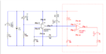
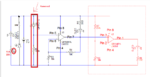
I googled, got some design for heart rate monitoring right now using that design but the only difference is the opamp. thay are using MCP602, but here at our place the MCP602 ic is very costly and very difficulty available.

So please is there anything like that lcd and detector. also what may be the change in design.

F80P3Y7GP6ZMBG3.LARGE.jpg
 
Last edited:

1.

You probably realize success depends on getting a usable waveform from your photodetector. You have to find a 'good operating point'. This involves what voltage you apply (bias), and through what resistance, etc.

The goal is to make it give a large change in voltage, from a small change in illumination.

I think this means you should configure the photodetector so it is slightly ON at all times.

2.

Your schematic shows filtering after the photodetector. Although pulse rates are 30 to 300 bpm (0.5 to 5 Hz), the heartbeat itself lasts about 1/10 sec. Therefore any filter you add must be able to pass 10 Hz.

3.

I suppose MCP602 is a specialty op amp? I think you can get by with an ordinary type.
 
  • Like
Reactions: ismbn

    ismbn

    Points: 2
    Helpful Answer Positive Rating
First of all, you need an opamp with a low input offset voltage, since that gets amplified along with everything else. For the MCP602 the offset is specified to be 2mV. That means with NOTHING on the input the output could be at 200mV. Since it's AC coupled that's probably not a problem. But, worse, that means your input may have to exceed 2mV before the output begins to move if the offset is in the negative direction.

I don't know what IS available in your area, but basically you want a 'precision' opamp. You don't need high frequency response, but you do need low offset. Also, since you've got a total gain of 10,000, you need to pay very close attention to the physical layout to avoid noise pickup


Thank you for all your response @FvM, @berry, @BradtheRad. Thaks for your precious time.

Sir BradtheRed
According your feedback.

1.
These are the feather detail.
I am using the 5V as Vcc over all for pulling led & diode and also the source of opamp. The transistor is just for switching i suppose, this is just to activate the led connected to it. This led i am driving using 100Ω to Vcc (instead of 150Ω), the led is bright enough i think to drive the photo diode.

2.

One more thing i forgot to mention above, is when i am passing the led up-down keeping the photo diode at fixed position its gives me 5Vpp correct waveform as the o/p like an motor encoder


3.

i am usiong LM324-N it shows input offset voltage is abovt 2mV typical & max 7mV....
do you think i should change the opamp ic....

4... Now as you suggested i will changing the filtering part....
but before that as you told, it is all dependent on the o/p of the photo diode.

5...
i think i am not getting the change in voltage waveform when i put my finger covering both(led & Photo diode), buit when i do as said on my point 2. doing up down.. i am getting the 3Vpp...
Right now i an removing the coupling capacitor which disconnect all circuit with photo diode. and testing the change in the o/p of Ph.Diode.


Please correct me where i am wrong....
 

Photo diodes are most sensitive to IR, and depending which part you are using, it will have a visible light filter.

Although the image on my phone is very small, I can still read that the schematic is specifying an IR LED.
So why are you using a red one?

Lastly, the photo diode's output is very small, the +5 volt feeding it should be very well decoupled.
 

OK.

I never know that photo diode is more sensitive to IR. i just want see the led is getting lighted or not, since i was not getting the correct waveform, there for i replace IR to red led. but the o/p is still not there...

Ok i am changing that red led to IR one...

one more thing i have this TRCT5000

https://www.vishay.com/docs/83760/tcrt5000.pdf


i will try both plane IR led and this TRCT5000 one more time. and i will update the result...

last time when i was tested it with IR led & TRCT5000. the response is some what like this time only. i will update the waveform next time also...

please tell me can i observe the response of the pulse on before amplification at photo diode...


Thank you...
 
Last edited:

Here are the images....

images 1 when i removing the finger...
**broken link removed**

image 2 is when i am passing the finger over the sensor.
**broken link removed**

images 3 is when i keep my finger covering the sensor
**broken link removed**

and the changes is schematic...
**broken link removed**

Please reply...
 

please tell me can i observe the response of the pulse on before amplification at photo diode...
Thank you...

Perhaps, if you can adjust everything for maximum response. This includes bias, brightness, position, etc.

Your schematic shows that the series R at the photodiode is now 10k. Did you experiment to find this value? Is this the value which yields greatest voltage swings from the photodiode? That is what you need.

The way I see it, it is a major achievement to get a response at all, considering the detector is trying to look within human tissue for sudden changes of blood flow.

Your images show that your project is responding very well to room light, when it gets to your photodetector (accidentally or deliberately). You may get better results by turning off room lights.

I suppose the little spikes are heartbeats (Image 3)? I see about 2 per grid. They are 1/7 the height of the tall hills. I think the tall hills are stray light getting at the photodetector.

To get reliable readings you need firm steady contact of the finger with the photodetector. Medical equipment has the wires built into clips for this purpose.
 
  • Like
Reactions: ismbn

    ismbn

    Points: 2
    Helpful Answer Positive Rating
Here are the images....

images 1 when i removing the finger...
1.jpg

image 2 is when i am passing the finger over the sensor.
2.jpg

images 3 is when i keep my finger covering the sensor
3.jpg

and the changes is schematic...
heart - Copy.jpg

Please reply...
 

Your attachments do not work so we cannot see the outputs of your circuit.
I found your circuit as a project in Google Images. It seems to copy an Instructable designed by a little kid who knows nothing about electronics.
We discussed the errors a few years ago. The photo diode amplifier does not work and the filters also do not work.
Maybe the designer connected the photo diode backwards causing it to be a tiny solar panel producing a positive output when it has light.

The reverse-biased photo-diode does nothing in the dark then its output is about +5V. The input coupling capacitor causes the input of the first opamp to be at about 0V then the output of the first opamp is also about 0V.
When there is light then the photo-diode leaks a small current causing it to send a negative pulse to the input of the first opamp. But since the input is at 0V it cannot go negative. If the input could go negative then it would cause the output to also go negative which is impossible since it is already as low as it can go.
Then your opamp needs to have an additional negative supply voltage so that when its input goes negative then its output can swing. Probably an inverting opamp circuit should be used.

Datasheets of photo diodes show an output of only 10mV into a resistor of 1 million ohms. Your bias resistor is only 33k ohms and your load is 68k which cause the output from the photo diode to be almost nothing. The project has some improvements showing a very sensitive photo transistor replacing the photo diode. The photo transistor has an output strong enough to drive your resistors. The photo transistor output is low when there is light and goes high in the dark which can activate the opamps.
 

It's well expectable that the sensor is sensitive to ambient light and reflectance variations. The interesting question is however if you see a signal that can be related to heart rate if your finger is on the sensor? The various waveforms shown in your latest post are almost meaningless if not annotated with a time base scale.
 

The voltage gain of each opamp is 101 times so with a total gain of 10,201 times the lousy old LM324 is amplifying its own high noise level.
I think it is also amplifying light pulses at 100Hz from mains-powered lights.
 

ok...

can this will work?
 

Attachments

  • Capture.PNG
    Capture.PNG
    47.5 KB · Views: 117

@Audioguru thanks for your precious time
please look into this

This is also not working.
i don't understand where i am wrong. i am very new in this opamp things. i don't know how to design as will as debug.
1.. i am getting supply 9V on pin 5 of above diagram.
2.. as per the document the led D3 should glow its not glowing at all
3.. no any amplification is observed on pin 7
4.. led D4 is also not at all glowing or blinking.
5.. and resistor R1 of 100ohm is getting heated
6.. No effect on either opamp's output when i vary R3 or R6

Please help
 
Last edited:

This is also not working.
1.. i am getting supply 9V on pin 5 of above diagram.
Positive 9V? Then your photodiode must be in a very bright light or is shorted.

2.. as per the document the led D3 should glow its not glowing at all
It will not glow because the output pin 7 is as high as it can go that is about 7.8V, because pin 5 is high. D3 will glow when pin 7 is almost at 0V.

3.. no any amplification is observed on pin 7
An amplifier does not amplify when its output is as high or as low as it can go.

4.. led D4 is also not at all glowing or blinking.
Output pin 1 is probably as high as it can go which is 7.8V and the LED D4 is burned out because its resistor value R8 is much too low. Its current was probably 72mA.

5.. and resistor R1 of 100ohm is getting heated
That is normal. Power dissipation heats a resistor with the voltage across it (9V - 1.8V= 7.2V for a red LED) times the current in it (7.2V/100 ohms= 72mA). Then it is dissipating 7.2V x 72mA= 0.52W. The resistor value is much too low causing a current of 72mA which will quickly burn out the LED. Most 5mm diameter LEDs operate at only 20mA so the resistor value should be 7.2V/20mA= 360 ohms or more.

6.. No effect on either opamp's output when i vary R3 or R6
Of course not. The other input voltages on the opamps are completely wrong so they cannot amplify.

To see what is wrong, disconnect the photodiode D2 so that R2 can allow input pin 5 to go low so that its output can also go low and light D3.
 
Last edited:
  • Like
Reactions: ismbn

    ismbn

    Points: 2
    Helpful Answer Positive Rating
now i have made this changes...

1. D3 is glowing. there is some waveform it PIN7, but its not clear
2. PIN 1 is by default at 5V
3. Sorry i missed to change the supply voltage in diag. but now i ma running all the things on 5V

i have uploaded the video because here its not allowing to upload the video.
https://youtu.be/0w1NUGKlb1M
Please
 

Attachments

  • Capture.PNG
    Capture.PNG
    54 KB · Views: 117

Your schematic shows an LM358 dual opamp. Which opamp are you actually using?
The output of an LM358 cannot go to +5V when it has a +5V supply. Its maximum output voltage will be about +3.5V since R8 has such a low value that the output current will be very high.

Since you removed the photo-diode and resistor to ground at the pin 5 input then this input will float high and cause the output pin 7 to also go high which will turn off LED D3.

Your video has no sound so we do not know what is shown on the oscilloscope. Is it voice or music?

- - - Updated - - -

Your schematic shows an LM358 dual opamp. Which opamp are you actually using?
The output of an LM358 cannot go to +5V when it has a +5V supply. Its maximum output voltage will be about +3.2V to +3.5V. R8 has such a low value that the output current will be very high.

Since you removed the photo-diode and resistor to ground at the pin 5 input then this input will float high and cause the output pin 7 to also go high which will turn off LED D3.
 

Your schematic shows an LM358 dual opamp. Which opamp are you actually using?
I am using LM358N dual opamp only.
...

The output of an LM358 cannot go to +5V when it has a +5V supply.
i am using 5V supply. and at the 1 stage of opamp i am getting 0.82V. and this waveform
finger not placed
snapshot-008.jpg

finger placed...
snapshot-009.jpg

and 0.1V at PIN 1... you were correct... i am not getting 5V at PIN1 there is some misunderstanding i was seeing at pin8 which is Vcc so i was getting 5V... Sorry:???:

That time i forgot to this.
So this is the correct schematic
Capture.PNG

When there is light then the photo-diode leaks a small current causing it to send a negative pulse to the input of the first opamp. But since the input is at 0V it cannot go negative. If the input could go negative then it would cause the output to also go negative which is impossible since it is already as low as it can go.
Then your opamp needs to have an additional negative supply voltage so that when its input goes negative then its output can swing. Probably an inverting opamp circuit should be used.

Do you this i should cange the opamp...
I have to Opamp 1 is OP07 which has negetive supply option
or
i should use MCP602
 

The LM358 is too noisy for your circuit. The inputs of an OP07 do not work at the low voltages in your circuit unless it has an additional negative supply.
An MCP602 needs a low power supply voltage and is also too noisy for your circuit.
 

Status
Not open for further replies.

Similar threads

Part and Inventory Search

Welcome to EDABoard.com

Sponsor

Back
Top