cybertron
Member level 3
Hi.
This is what i been try to do. But? didn't have or known the right parts to use.
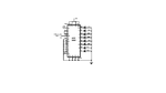
I seen this circuit and want to know.Both circuit enclosed.
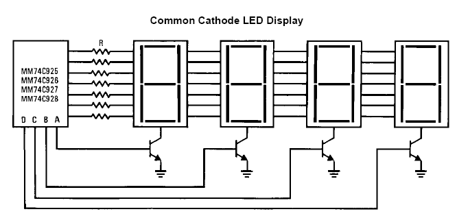
1.How do I use (4) 7-segment displays with this circuit setup.
Then I need the displays to function from left to right the right display will be the last digit to display its output number.
So the functioning needs to work like this.decoder displays first number whether 0-9 that number stays on then the decoder display second number on second display that number stays on then the third number and the same for the last number whether 0-9 for each display. they will all stay on until a new set of number are sent to the decoder and decodes those numbers.Or a reset momentary switch reset all displays to zero.Can you send me a revised schematic for this setup for my needs to the MULTIPLEXED BCD 7-SEGMENTS DRIVER CIRCUIT. PLEASE HELP.
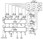
2.Then interface the ADC 0808 output too the CD4553 input.How do I do this.
Maybe I still need to add another chip to interface the ADC TO the 4553 in the second part of the circuit.
This is what i been try to do. But? didn't have or known the right parts to use.
I seen this circuit and want to know.Both circuit enclosed.
1.How do I use (4) 7-segment displays with this circuit setup.
Then I need the displays to function from left to right the right display will be the last digit to display its output number.
So the functioning needs to work like this.decoder displays first number whether 0-9 that number stays on then the decoder display second number on second display that number stays on then the third number and the same for the last number whether 0-9 for each display. they will all stay on until a new set of number are sent to the decoder and decodes those numbers.Or a reset momentary switch reset all displays to zero.Can you send me a revised schematic for this setup for my needs to the MULTIPLEXED BCD 7-SEGMENTS DRIVER CIRCUIT. PLEASE HELP.
2.Then interface the ADC 0808 output too the CD4553 input.How do I do this.
Maybe I still need to add another chip to interface the ADC TO the 4553 in the second part of the circuit.
Attachments
Last edited: