Continue to Site

Welcome to EDAboard.com

Welcome to our site! EDAboard.com is an international Electronics Discussion Forum focused on EDA software, circuits, schematics, books, theory, papers, asic, pld, 8051, DSP, Network, RF, Analog Design, PCB, Service Manuals... and a whole lot more! To participate you need to register. Registration is free. Click here to register now.

12V power dropped with load

Status
Not open for further replies.

LeeSengTang

Newbie level 5
Joined
Dec 26, 2014
Messages
8
Helped
0
Reputation
0
Reaction score
0
Trophy points
1
Activity points
66
Hi All! Im beginner @ circuit field.
I hav a problem with control dc 24v motor by pic16f877a.
My circuit is as follows.
circuit.png
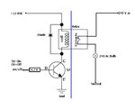
Pic16f877a output pin drive mosfet bss138 & bss138 drive relay coil.
Pic control dc motors rotate direction according to IR sensor signal.
Im using 24v switching power by TOP245,& 12v by 7812,& 5v by 7805.
It works well without motor, but with motor 12v power dropped to 6v,5v power dropped 2v & IR sensor short & pic16f877a short.
Whats th reason?
Pls help me!:-(
 

Hi...

What is relay coil resistance?

The mosfet can sustain only 220mA. If the coil resistance is low mosfet have chance to damage..

So try to do the changing the mosfet with higher current rates.. (ex: above 1 A)
 
I think your diode placement is wrong you put diode in series it should be in parallel across the relay coil you can see the attached image
 

Attachments

  • GIHhS.jpg
    GIHhS.jpg
    16 KB · Views: 119
Hi amayilsamy!
My relay coil resistance is 400 ohm.
Relay coil drive voltage is 12v, so current is 30mA.
So I think Mosfet is full to drive relay coil.
 

Your report says that the 24V switching power supply hasn't sufficient current capability to drive the motor. Not related to relay, PIC etc. You can easily check by connecting the motor to the power supply directly.
 
Your report says that the 24V switching power supply hasn't sufficient current capability to drive the motor. Not related to relay, PIC etc. You can easily check by connecting the motor to the power supply directly.

Hi, FvM. U mean tht my switching power is unsufficent to provide current required to drive motor?
As a matter of fact I refer to the sample board.
In Sample board, motor works well by switching power.
I design my project as the same sample , but my board sometimes works well, but a few seconds later 12v power drop and pic stops.
I havent switching transformer , so I use sample boards transformer by wireing.
Pls advice me! What seems to be problem?
 

Sorry, but the voltage drop reports are too unclear to give helpful suggestions from a distance. The 12V regulator output would only drop if the input voltage falls below e.g. 13 V. Similar with 5V regulator.

PIC operation can be nevertheless affected by relay contact arcing if the processor circuit has unsufficient bypassing, or MCLR or serial lines pins pick up interferences.
 
According to ur opinion, I connect 24v power supply and 12v,5v power supply separately externally.
At first I common their ground, then 12v and 5v power supply dont drop but PICs output pin stoped.
I check it by connect led.
So I separated their ground i.e 24v, 12v, 5v, then my project works well.
Whats the reason?
 

Hard to say without seeing the circuit layout. May be the motor current is causing ground voltage drops?

What's against using separated grounds?
 
My reference board is using 24v,3A power switching circuit and 12v by 7812, 5v by 7805.
At first I havent power ,so I use reference boards power.
But unfortunately I unprovide th power Vdd, only provide 5v power to Vref pin.
Then Pic outpin dropped 2.5v, 7805 and 7812 overheated.
After that I provide correct 5V power to PIC , my circuit works well without motor.
But with th motor , a few seconds later 7812 and 7805 overheated and voltage dropped.
Whats th reason?
 

Apparently a component is shorting the 5V supply. May be a processor latch-up is triggered by an input voltage below ground or above Vdd on any pin. This can be a circuit/wiring fault. Or the processor has been damaged by previous "mistreatment".
 
Apparently a component is shorting the 5V supply. May be a processor latch-up is triggered by an input voltage below ground or above Vdd on any pin. This can be a circuit/wiring fault. Or the processor has been damaged by previous "mistreatment".
Accoding to ur opinion, I exchanged th PIC and BSS138, 7805.
But with motor, 7812 and 7805 overheated.
My 12v,5v power supply circuit as follows.power.png
After removing power , I check power element then 7812's 10 ohm resistor burnt and its value is 0 ohm.
What do u think that about back EMF of motor generator and relay coil?
Else switching power's componet damaged my "mistreatment" and transformer?
But switching powers output voltage correctly 24v.
I cant guess my fault.
Pls help me!
 

Try with two different power supply one 24v SMPS for only motor supply and another 24v smps to supply 7812 and 7805 and check the result.
As respected FvM said it is hard to identify the what is the problem from distance which make voltage drop so do step by step debugging.
 

Hi, All!
I found new thing.

I exchange th motor direction switching.

Originally according to th IR signal, motor direction decided.

PIC16f877a RB7 is sensor input & I use PORTB interruption over change, RB2, RB3 is motor drive output.

I input th 0, 5v signal manufactually instead of IR signal to RB7, my project works well.

But with the IR signal , my pic circuit shorted and IR sensor TSOP1838 damaged.

Pls let me know my fault!
 

Hi, FvM! Thank you for ur trouble.

My Pic schematic circuit is as follow.
pic.png

And my relay drive circuit & power circuit as follows.
POWER_24,12,5v.png
relay.png

Externally IR sensor signal entered to RB7.

According to th signal , Relay1, Relay2 converted(0, 5v).
 

Does "direction switching" involve immediate switching from foward to reverse or vice versa? This causes doubled inrush current and contact arcing. You can reduce contact arcing by installing four free-wheeling diodes across the relays contacts or a bidirectional TVS diode across the motor. But inrush current still happens. It would be better, also saving gear lifetime, to introduce a time delay between forward and reverse motor run.
 
Status
Not open for further replies.

Part and Inventory Search

Welcome to EDABoard.com

Sponsor

Back
Top