Continue to Site

Welcome to EDAboard.com

Welcome to our site! EDAboard.com is an international Electronics Discussion Forum focused on EDA software, circuits, schematics, books, theory, papers, asic, pld, 8051, DSP, Network, RF, Analog Design, PCB, Service Manuals... and a whole lot more! To participate you need to register. Registration is free. Click here to register now.

Connecting converter to the inverter

Status
Not open for further replies.

sam781

Full Member level 4
Joined
Oct 22, 2011
Messages
212
Helped
7
Reputation
14
Reaction score
7
Trophy points
1,298
Activity points
2,757
I've made a bridge Converter and an Inverter.
Converter: 12v to 400v dc (practically measured using DMM after applying filter)
Inverter: Sine PWM inverter. Checked output using 12v supply. output is not that much good. but I want to check with higher volt (400v).

Now, to get both the circuits (converter and inverter) work I'll have to have a common ground. how can I connect the converter control circuit's ground to the output (400v) ground?
 

Is this a power supply created across a full H-bridge? Then it must be treated as independent. Devices which it powers should be kept isolated from preceding circuitry.

There may be exceptions if you connect them through a high impedance to preceding circuitry.
 

Yes, full H-bridge.
If I want to keep it isolated from preceding circuity, I'll have to use a separate 12v dc supply to drive H-Bridge MOSFETs. But again, the 12v supply ground has to be connected to the 400v dc ground.
 

converter & inverter_Circuit3.png

Should I not use the connection (red wire) as shown in the above figure?
 

connecting ground of the control circuit to a power circuit at 400V level puts a lot of risk to your design. In my opinion, it is better to use isolated dc source along optocouplers to drive your switches on high voltage side.
 

Should I not use the connection (red wire) as shown in the above figure?

You may be able to drive Mos1 and Mos3, if your MCU is able to put out sufficient voltage.

However Mos2 and Mos4 will need much higher volt levels to drive the gates. Or else a different arrangement using Pmos and Nmos.

Caution: If any of the mosfets ever have their gate perforated by high voltage, that high voltage will go right to your microcontroller. How much money is it worth?

I agree with kappa_am's post #5. Is your power source a battery? It is a hazard to let high voltage get into a lead-acid battery. A spark inside could cause an explosion.
 

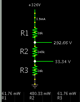
There's a chance you won't need all those extra windings and diodes. Consider that you could derive a stack of volt levels from a resistive divider. This can work because you merely need miniscule current to drive mosfets.

Normally, if you need much current then you would need high watt ratings for the resistors, due to heating.

5333499600_1420680498.png


So suppose where there is R1 and R3, you put mosfets (or components to control mosfets). You would probably want them to operate within a few volts of the supply rails. Above is an example of the range of impedances that would be involved, internal or external.
 
  • Like
Reactions: sam781

    sam781

    Points: 2
    Helpful Answer Positive Rating
Thanks a lot. Very good suggestion indeed. In the technique, I'll have to use high low side driver (IR2110). Also I'll have to get 20v dc to be used as Vcc as Ho or Lo of the driver has to be belwo 20v (max Vgs of IRF840 is 20v). 5v dc is also requied to be used as Vdd of the driver. Is my understanding okay?
 

To make further progress, you'll have to design a driver circuit, and post the schematic. Answers will have to come from someone with more knowledge than I have.

The optocoupler idea (post #5) is safe and sensible.

Other people have constructed this kind of high voltage H-bridge. You may want to find out how what methods they use to drive them, and what obstacles they encountered.
 

Considering the post #5 I've designed the circuit (post #7) using optocoupler. It will minimize the complexity of using high and low side MOSFET driver.
 

Please look at datasheet of your switches and make sure you provide enough charge according to your switching frequency! 1K resistor on gate seems high. you may be obliged to use driver after optocoupler.

Good luck
 

I'll replace 1k resistor with 22ohm.
 

according to the datasheet of the your opto 22 is too small use a 120 or 150 resistor.

good luck
 

according to the datasheet of the your opto 22 is too small use a 120 or 150 resistor.

good luck

Oh!
Actually, I didn't concentrate on those important things (output current capability of Opto and the resistance). I picked up an optocoupler and design the circuit. But now I should consider all those things. Max collector current of 4N35 is 100mA. I think I should consider for more current for the MOSFET gate to turn on faster. Also the maximum operating frequency is also required to be above 30kHz.

Can you please suggest a good opto ic which will meet up my requirements (eg, around 1A output current, about 50kHz frequency of operation)?
 

I didn't find TLP700H locally. I purchased TLP350. Hope it will be okay.
 

I've faced a strange problem. When I measure the secondary coil voltages (3 coils for gate drive) it is showing around 16 peak voltage (and 32 p-p voltage). But when I connect it to Bridge rectifier (4 1N5819 diodes) it shows around 40v dc without the filter circuit. How it could be possible?

Transformer data-
primary turns: 4
Secondary terns (for gate drive): 5

one more turn has been used to get a little more voltage than the 12v primary input. As the MOSFET gate max voltage is 20. So, output voltage 16 should be good enough.
 

are your waveform at the output a sinusoidal? check it
connect a load to the output of the bridge and measure the voltage again. I guess you measured when no load is connected to the output.
 

Status
Not open for further replies.

Similar threads

Part and Inventory Search

Welcome to EDABoard.com

Sponsor

Back
Top