Continue to Site

Welcome to EDAboard.com

Welcome to our site! EDAboard.com is an international Electronics Discussion Forum focused on EDA software, circuits, schematics, books, theory, papers, asic, pld, 8051, DSP, Network, RF, Analog Design, PCB, Service Manuals... and a whole lot more! To participate you need to register. Registration is free. Click here to register now.

Need help with wiring and product usage

Status
Not open for further replies.

steve23h

Newbie level 5
Joined
Dec 18, 2014
Messages
8
Helped
0
Reputation
0
Reaction score
0
Trophy points
1
Activity points
70
To give a brief background of what I am trying to do keeping it as simple as I can:

I build machines that are driven by 5VDC photosensor's among other components. What I am trying to accomplish is taking the 5 volt sensor signal, which is driven by a logic board, and write a program using that signal. Currently I use a DL-06 PLC with a CMORE touchscreen. I have my program written already now I need my signal to cooperate in order to make my program work. So far I have tried a 5VDC coil mechanical relay and a solid state relay and they have both not given me the results I am looking for. Unfortunately I cannot take the signal straight from my sensor and activate my program because the PLC requires a 12-24 VDC input where my sensor only supplies 5 volts.

Now that is out of the way, I have landed on using a LM324 Single Supply Quad Amplifier IC. I have spoken to a rep from the company that makes this product and he assures me I will be able to make it work, I am just trying to get a little more information on how I can wire it.

Any help would be much appreciated. If there is any more information that is needed in order to assist me I would be more than happy to supply it.

Thank You
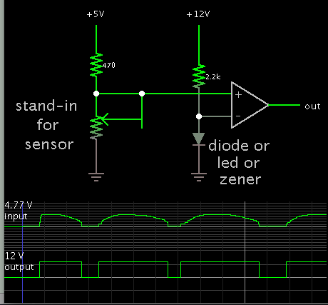
 

Typical method to read a sensor with an op amp:

2749321600_1418877493.png


The potentiometer was dialed up and down to produce different volt levels.

The op amp is operated as a comparator. It can have a single supply (but check the spec sheet to make sure 24V isn't too high).

Supply voltages can be different. The grounds must be connected.

The diode or led or zener serves as a voltage reference. You need to be able to set a reference level, in order to detect when your sensor crosses above or below it.
 

Thank You I appreciate the diagram, I am a little rusty on my electronics from a diagram perspective, would you mind going into a little more detail as to what each termination will be. As I see it I am going to bring a 5 volt source (which I think would be my sensor) and and a 12 volt, or in my case 24 (which the IC can handle up to 32 volts), and run them through a resistor, diode, IC, and then my output? Am I correct in this?
 

run them through a resistor, diode, IC, and then my output? Am I correct in this?

Wires connect only at the white dots. The sensor does not contact the diode.

My schematic is more of a conceptual drawing. It is a basic design which you can experiment with, and develop a working circuit.

Concept of operation:
The LM324 works this way (as do ordinary op amps). The output voltage goes high or low, depending on which input is higher. A fixed voltage is applied to one input. Your sensor voltage is applied to the other input.

You don't have to use the exact same arrangement. You may prefer the output to act in the reverse manner from my schematic. You might find it better to connect your sensor to the inverting input. Etc.

You may decide you want the output voltage to change gradually. Then you would add a feedback resistor network.

Etc.

As you provide more information about the sensor, logic board, desired output range, etc., you can expect more replies.
 

Ok I am getting it a little better now.

I can use the diagram that I have for my LM324 to figure where to put my sensor wire. On the 5 Volt end there is two resistors shown, what would be the value of the resistor that is not labeled. Would this be 470 as well, or a different value?
 

All my values are only examples. Including my 470 ohms and my potentiometer being 10k ohms, an example.

Further progress in your own design depends on the details of your sensor.

How many wires does your sensor have?
2, 3, 4?

If 2 wires, then is it the type that changes its own resistance? Does resistance increase with increased temperature? You will need to experiment to find what value resistor you should put inline with it.

If 3 wires, then are two of them connected to +5V and 0 gnd?
What is the voltage range that comes from the signal wire?

Etc.

taking the 5 volt sensor signal, which is driven by a logic board

Regarding this logic board... What is its function in relation to the sensor? Does it supply power? Act as a signal conditioner? Receive the signal? Etc.
 

I will give as much information as I can regarding the logic board. I am certainly not an expert when it comes to this, but with a little guidance I am confident I can get something working.

The logic board gets turned on by a 5 volt power supply. There are many functions that it serves (turning motors on and off through outputs going to solid state relays, activating and deactivating solenoids, etc.). Each sensor has 3 legs on it, but only two of which are used. When I test the wires coming out of my harness that goes to each sensor, I have 5 volts when the sensor is unblocked, and 0 volts when the sensor is blocked, there is also an LED on the board that turns on and off when each sensor is blocked (one for each sensor).

Regarding the diagram that you sent, I am a little confused to where each connection is going to go, I know you said each dot on the diagram is in reference to a wire or connection, but I am not sure which goes where.

I apologize for being a little on the amateur side but any more help you can give I would truly appreciate.

Thanks Again
 

Each sensor has 3 legs on it, but only two of which are used.

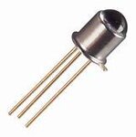
Likely it's a phototransistor. The unused leg is the bias leg. It gets photons instead of electrons.

Does it look like this?

DownloadedFile.jpeg

Its internal resistance goes down when illuminated.

(I mistakenly talked about response to temperature in post #6.
I meant illumination.)

When I test the wires coming out of my harness that goes to each sensor, I have 5 volts when the sensor is unblocked, and 0 volts when the sensor is blocked, there is also an LED on the board that turns on and off when each sensor is blocked (one for each sensor).

Regarding the diagram that you sent, I am a little confused to where each connection is going to go, I know you said each dot on the diagram is in reference to a wire or connection, but I am not sure which goes where.

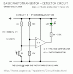
For comparison here is another schematic (grabbed off the internet).

Basic_PhotoTransistor_Schematic.GIF

It has two 10k resistors, arranged to divide the supply voltage in half. This may turn out to be fine for your application.

As you can see, a range of values is stated for resistor R1 (above the phototransistor Q1). This is where you must experiment. The goal is to change the volt level at the node between R1 and Q1. The changes must be sufficient so that voltage swings high when dark, and low when illuminated.

At no time should you allow more than 1 or 2 milli-Amps through the phototransistor. Hence with a 5V power supply, R1 should always be greater than 5k ohms.
 

Ok that diagram is a little more friendly. Unfortunately I do not have a 12V power source on my machine, only a 5 and 24. I imagine my resistor value would grow given I am using a 24VDC power supply instead of a 12? Here is this tricky part I think though. I need to be able to keep the sensor in the same circuit it already is in because the logic board still needs to do what it does. Would this pose a problem having the sensor both go into the logic board and my new circuit I am installing?

I am hoping this isn't a losing battle for what I am trying to accomplish.

Thank You
 

Perhaps dropping in a bit late, but aren't you better off with a sn 7407? From your information I deduct that you have some switshing device, ie. a phototransistor that toggles between 0 and 5 Volts. And a receiving device, a PLC running at 24 Volts. Is that correct?
A 7407 is designed for this job. If your PLC can pull up its inputs you're lucky, connect the phototransistor to a input of the 7407 and the apropriate output to the PLC and your'e done.
Worst case you must add a suitable resistor (Say 22 k) from the 24 Volt to the PLC input. (Making a pull up.)

H.N.
 

Yes that is exactly what I am looking to do. I will do my research to see if I have this in stock and wiring.

Thank You

- - - Updated - - -

Would you have a suggestion to how my wiring should go?
 

Yes that is exactly what I am looking to do. I will do my research to see if I have this in stock and wiring.

Thank You

- - - Updated - - -

Would you have a suggestion to how my wiring should go?
Steve, I am not sure you refer to my response about the SN 7407. But if so:
Find the manual of the SN 7407 on the internet. The drawing will tell you there are seven input/output pairs, pin one is input with pin two as complementing output. Etc.
Connect pin 14 with 5 Volts, pin 7 with ground.
The 7407 is from the 7400 TTL family, inputs are activated by drawing current out of the port. (max 1.6 mA)
Test the output from from the photosensor if it can sink (absorb) 1.5 mA current:
The photosensor is dark, 0 Volt. Connect a 2700 Ohm resistor between the 5 Volts and the output of the photosensor. Is the voltage over the sensor less than 1 Volt?
If yes, you can connect the photosensor straight away to the input of a ' 7407 port.
(If not, let us know, you will need a different approach, with a LM 339 perhaps.)
The output is an open collector, capable of sinking 30 mA. (But not all outputs at the same time! Between you and me, keep the max sum of currents below 100 mA.)
Connect the output of the port to the input of your PLC and via a resistor to the 24 Volts line.
I would start with a value of 22 k Ohm, or 27 k Ohm, if the environment is noisy, you might go lower
Hope to be of help,
wish you a happy and successfull new year
Harry.
 

Status
Not open for further replies.

Part and Inventory Search

Welcome to EDABoard.com

Sponsor

Back
Top