Continue to Site

Welcome to EDAboard.com

Welcome to our site! EDAboard.com is an international Electronics Discussion Forum focused on EDA software, circuits, schematics, books, theory, papers, asic, pld, 8051, DSP, Network, RF, Analog Design, PCB, Service Manuals... and a whole lot more! To participate you need to register. Registration is free. Click here to register now.

A question about the PHOTO-FLASH capacitor

Status
Not open for further replies.

ghanbari

Newbie level 4
Joined
Oct 27, 2009
Messages
5
Helped
0
Reputation
0
Reaction score
0
Trophy points
1,281
Location
iran
Activity points
1,310
Hello,
I want to make a circuit using a photo-flash capacitor rating above to 100uf/100v, but here in my country (Iran) i cant find this kind of capacitors. Can i use several normal electrolytic capacitors in parallel instead of it? Do several identical capacitors in parallel work as a single Low-ESR one like a Photo-Flash capacitor? Can they tolerate High currents without extreme heating?:?:
thank you very much.
 

Chinese made flash units just use ordinary capacitors so I see no reason why you can't do it as well. Yes, you can use lower value capacitors (but not lower voltage ones) in parallel and it does reduce the effective ESR.

Brian.
 
Indeed, i am going to build a EDM (Electric discharge machining) system that really needs a capacitor (or capacitor bank) that be able to work continuously several hours with high current. It is different in contrast with flash unit applications.
 

For EDM you would be better to have a large (>>100) array of 10 uF 100V electrolytic caps in parallel. This will help reduce inductance . SMD will have a much higher SRF which also is important for ionization ripple frequency but generate more EMI.

I recommend 10mF rather than 10uF.

The key to smooth EDM is a HV spark to trigger the arc and then a low voltage low ESR high current for controlled Joule discharge like Xenon HID circuits. Too high a voltage will result in excess ripple current and ESR self heating I^2R dissipation results in rapid temp rise and early failure with 10x failure rate for every 10'C rise up to rated temp then faster after this. Air arc is approx 1kV/mm depending on electrode sharpness.

You can regulate the pulse duration with SRF or series reactor LC tuned circuit, but heat loss in regulating current limit ought to be external to caps. and in a carbon & tungsten filament resistor for (NTC) so as regulate heat transfer to tungsten electrode interface.

Best is to use Plastic Caps for low ESR , not the kind used for Motor Start which have higher ESR.

PFC rack mounted line caps are always made with plastic ( PU or PE) for the electric utility industry. Look there.
 
Thank you all.:thumbsup:

- - - Updated - - -

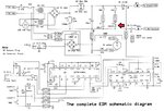
Here is the schematic of EDM system that i am going to build it:
Untitled2.jpg
Capacitor C3, is needed for making coarse EDM cuts and this electrolytic capacitor should be a photo or strobe flash capacitor. The ratings should be a minimum of 100VDC @ 80uf (Schematic and information reference: "The EDM How-To Book" by Ben Fleming).
The main problem is that, the mentioned capacitor is not available at my country and thus i want to substitute it by an array of parallel normal capacitors. I need to know that what kinds of capacitors should be used. 10 * 10VDC/10uf caps, or 10 * 10VDC/10mf caps, or something else? :?:
 

That seems to be a much lower power machine than SunnySkyguy visualizes. It has minimal arc generation and the current should be lower than about 3A to keep other components within their ratings. I would guess therefore that the capacitor specification isn't criticaly important.

Certainly do not 'stack' 10V capacitors to achieve a higher voltage rating. If you connect them in series to increase the voltage rating you will face three problems, the overall value will be decreased, the ESR will be increased and the voltage may not be shared equally betwen them.

You can connect 100V capacitors in parallel, this adds their values together and reduces their effective ESR. For that you need say 10 * 10uF/100V or 5* 20uF, some combination of equal values that makes up a total of 100. I would not expect the total capacitance needs to be very accurate, you can probably go quite a bit higher although I wouldn't go too much lower as it will reduce your arc power. Note that the original schematic is 160uF !

Brian.
 
Oh, excuse me Brain, I wanted to write 100VDC but i have mistaken:oops:
Anyway, your answer is good and perfect and i will do so.
thank you very m
 

Status
Not open for further replies.

Similar threads

Part and Inventory Search

Welcome to EDABoard.com

Sponsor

Back
Top