Canadari
Newbie level 3
Hello,
I own a hobby cnc machine from China called HY3040 and you can find a lot of them on ebay, but non of them have similar controller boards inside. Each comes with different ones and usually when you first buy them, they come with cheapest boards you should anyway change it. In my case I have to, because the breakout is burned.
I must search to find a good board but for now to put the machine back to work I have another cheap one available which also got off ebay.
Now to replace the burned breakout board with the new one, I have two main problems:
1. no documentation!
2. knowledge insufficiency
Generally, I know that there are control wires S,N,D,E between the breakout board and the controller board per axis, and from there each axis controller board is connected to the stepper motor with A+ A- B+ B- wires. Here inside the control box I found strange wiring to me. With some more knowledge I could easily trace and connect but I found it better to not to do trial / error but to turn to specialists in the forum.
Chinese seller sent what he calls "manul", but in that there is a little information about a different breakout board than what is inside the machine control box!
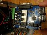
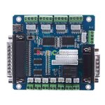
I attach photos of burned and new boards. As you see on the photo of the burned board, a double-row 20P cable connects the main motor controller (which has 3 motors connected to for A+ A- B+ B-) to the breakout. Beside table there is a pinout printed:
BS, BD
NC, RL
XD, YS
XS, YD
XE, YE
AD, ZS
AS, ZD
12, 12
GD, GD
VC, VC
Questions:
1. On the burned board there is nothing written around the motor wires socket at the side of the board, but I guess that those wires are XE, XD, YE, YD, ZE, ZD, how could I be sure please?
2. As first step I only want to put X axis to work. On my new breakout board, I have XE, XD, XS, XN pins and X-Limit with 2 pins totally 5 pins. On the old board I have 2 pins connected directly to the motor, and 3 ones (XS, XD, XE) connected by the 20P cable, also 5 in total, but how should I connect them correctly and what I have to measure / know?
The photo with my fingers in, shows the burned motor! The photo with pins information written around, shows the new board.


Please guide me.
I own a hobby cnc machine from China called HY3040 and you can find a lot of them on ebay, but non of them have similar controller boards inside. Each comes with different ones and usually when you first buy them, they come with cheapest boards you should anyway change it. In my case I have to, because the breakout is burned.
I must search to find a good board but for now to put the machine back to work I have another cheap one available which also got off ebay.
Now to replace the burned breakout board with the new one, I have two main problems:
1. no documentation!
2. knowledge insufficiency
Generally, I know that there are control wires S,N,D,E between the breakout board and the controller board per axis, and from there each axis controller board is connected to the stepper motor with A+ A- B+ B- wires. Here inside the control box I found strange wiring to me. With some more knowledge I could easily trace and connect but I found it better to not to do trial / error but to turn to specialists in the forum.
Chinese seller sent what he calls "manul", but in that there is a little information about a different breakout board than what is inside the machine control box!
I attach photos of burned and new boards. As you see on the photo of the burned board, a double-row 20P cable connects the main motor controller (which has 3 motors connected to for A+ A- B+ B-) to the breakout. Beside table there is a pinout printed:
BS, BD
NC, RL
XD, YS
XS, YD
XE, YE
AD, ZS
AS, ZD
12, 12
GD, GD
VC, VC
Questions:
1. On the burned board there is nothing written around the motor wires socket at the side of the board, but I guess that those wires are XE, XD, YE, YD, ZE, ZD, how could I be sure please?
2. As first step I only want to put X axis to work. On my new breakout board, I have XE, XD, XS, XN pins and X-Limit with 2 pins totally 5 pins. On the old board I have 2 pins connected directly to the motor, and 3 ones (XS, XD, XE) connected by the 20P cable, also 5 in total, but how should I connect them correctly and what I have to measure / know?
The photo with my fingers in, shows the burned motor! The photo with pins information written around, shows the new board.


Please guide me.