darrylcapulla
Junior Member level 1
- Joined
- Dec 15, 2014
- Messages
- 19
- Helped
- 0
- Reputation
- 0
- Reaction score
- 0
- Trophy points
- 1
- Location
- Pili, Camarines Sur, Philippines
- Activity points
- 145
Hello,
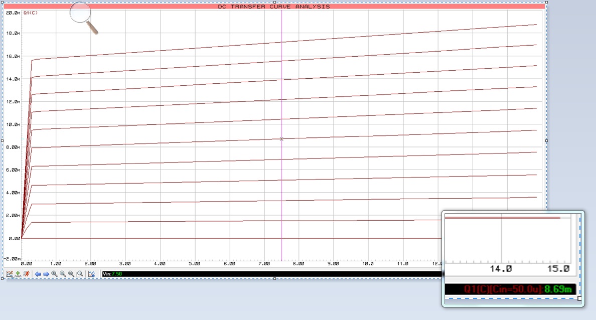
Can anyone help me to Draw a DC Transfer Curve Analysis for 2n3904??
15V or Higher for Vce.. Im Using Proteus 8..
Sample of DC Transfer Curve
Can anyone help me to Draw a DC Transfer Curve Analysis for 2n3904??
15V or Higher for Vce.. Im Using Proteus 8..
Sample of DC Transfer Curve