Continue to Site

Welcome to EDAboard.com

Welcome to our site! EDAboard.com is an international Electronics Discussion Forum focused on EDA software, circuits, schematics, books, theory, papers, asic, pld, 8051, DSP, Network, RF, Analog Design, PCB, Service Manuals... and a whole lot more! To participate you need to register. Registration is free. Click here to register now.

Calculate impedance PCB tracks

Status
Not open for further replies.

www111

Junior Member level 3
Joined
Oct 10, 2012
Messages
29
Helped
0
Reputation
0
Reaction score
0
Trophy points
1,281
Activity points
1,541
Hi all,

I have different results of calculation and I don't know which one is the right.

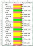
I'm trying to calculate the 50 Ohm impedance on L3,L4,L7,L8 of this stack-up:
stackup.jpg

Do I threat the L3,L4,L7,L8 as a Asymmetric Stripline?
what calculator should I use?
what is the width of 50 Ohm line on L3 if the Er=4.3?

Best Regards.
 

The Saturn PCB toolkit has been mostly suggested for similar purposes.

It should be noted that the traces on the said layers are no clean asymmetrical stripline because the impedance is affected by traces on the other signal layer. You get best results by defining orthogonal routing directions on the adjacent layers.
 

Another good software is from polar instruments i am using si9000. According to this calculator the line on L3 is 505um for 50 ohm.
 
From this layers stack-up,if the thickness of L2 to L3 is 150um,the width of line for 50ohm impedance on L3 should be 200um.
Myabe other layers stack-up adjust a little to reach the impedance.

PS:You can use SI8000/SI9000 software to calculate it.
 
Last edited:

Status
Not open for further replies.

Part and Inventory Search

Welcome to EDABoard.com

Sponsor

Back
Top