Continue to Site

Welcome to EDAboard.com

Welcome to our site! EDAboard.com is an international Electronics Discussion Forum focused on EDA software, circuits, schematics, books, theory, papers, asic, pld, 8051, DSP, Network, RF, Analog Design, PCB, Service Manuals... and a whole lot more! To participate you need to register. Registration is free. Click here to register now.

Stability of PA by Impulse Response

Status
Not open for further replies.

f_t

Member level 4
Joined
Jun 30, 2014
Messages
75
Helped
1
Reputation
2
Reaction score
1
Trophy points
8
Activity points
633
Stability of PA by applying a step input

Friends,

I am evaluating the stability of my PA. K_factor ( stab_fact(S) ) and B1 (stab_meas(S)) are more than 1 and 0, respectively at all frequencies. So my PA should be stable.
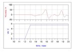
I have done another test too. I have applied an step signal at input and seen output voltage. As it is clear in the figure it oscillates and is not stable!!! why?!!! I have used a transient analysis for step response.

Using step response is a mistake to evaluate stability or my circuit is not really stable?!
Could you help me?
Untitleddd.jpg
 
Last edited:

How many stages are there on your PA ?? Stability factors are valid for single stage amplifiers only.
Also, small signal stability does NOT mandatorily bring large signal stability because large signal s-parameters different than small signal s-parameters which are used to compute K ( or Mu ).
 
  • Like
Reactions: f_t

    f_t

    Points: 2
    Helpful Answer Positive Rating
How many stages are there on your PA ?? Stability factors are valid for single stage amplifiers only.
Also, small signal stability does NOT mandatorily bring large signal stability because large signal s-parameters different than small signal s-parameters which are used to compute K ( or Mu ).

It has just one stage.
"small signal s-parameters which are used to compute K" : I am using nonlinear model of the transistor. So, s- parameters calculated by ADS (the software) are not small signal.
 

It has just one stage.
"small signal s-parameters which are used to compute K" : I am using nonlinear model of the transistor. So, s- parameters calculated by ADS (the software) are not small signal.

It's not correct.S-parameter simulation in ADS -by default- computes always small signal s-parameters by linearizing ALL devices in the circuit at their vicinity of DC operating points.It's essentially nothing but a kind of AC simulation technique.Using nonlinear model doesn't change this.Therefore there is another palette LSSP to do "Large Signal S Parameters" simulations.
 
  • Like
Reactions: f_t

    f_t

    Points: 2
    Helpful Answer Positive Rating
how about an ideal stepped RF input, and look for transient phase shifts and over/undershoots at the output. An unstable amp will be very "ringy". another option would be stepped RF input, and look at the output spectrum for odd spurious frequencies showing up.
 
  • Like
Reactions: f_t

    f_t

    Points: 2
    Helpful Answer Positive Rating
It's not correct.S-parameter simulation in ADS -by default- computes always small signal s-parameters by linearizing ALL devices in the circuit at their vicinity of DC operating points.It's essentially nothing but a kind of AC simulation technique.Using nonlinear model doesn't change this.Therefore there is another palette LSSP to do "Large Signal S Parameters" simulations.

You said correctly BigBoss. I changed s-param to LSSP and again tried to see k factor and B. They did not show a stable PA. K factor was lower than 1 in some frequencies, however it was more than 1 by s-param (small signal) simulation. Thank you.

- - - Updated - - -

how about an ideal stepped RF input, and look for transient phase shifts and over/undershoots at the output. An unstable amp will be very "ringy". another option would be stepped RF input, and look at the output spectrum for odd spurious frequencies showing up.

Thank you biff44.
How can I see transient phase shift in ADS? When apply a step, I can just see vload not phase of vload in ADs. Do I have to add another probe for that?
Besides, what is base of your analysis? Why does an unstable amplifier have a ringy phase?
 

Status
Not open for further replies.

Part and Inventory Search

Welcome to EDABoard.com

Sponsor

Back
Top