Continue to Site

Welcome to EDAboard.com

Welcome to our site! EDAboard.com is an international Electronics Discussion Forum focused on EDA software, circuits, schematics, books, theory, papers, asic, pld, 8051, DSP, Network, RF, Analog Design, PCB, Service Manuals... and a whole lot more! To participate you need to register. Registration is free. Click here to register now.

[General] any way to get a wifi network from wifi SD cards using pic microcontroller

Status
Not open for further replies.

Tareq Domi

Junior Member level 2
Joined
Nov 16, 2014
Messages
22
Helped
0
Reputation
0
Reaction score
0
Trophy points
1
Activity points
167
hello guys ,

a wifi SD card gives you a wifi network once you plug the card into a digital camera or any device that support normal SD card .
check this : https://goo.gl/sqvErL

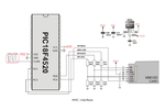
in my project , i need to operate that wifi network from the wifi-Sd card using controllers ( i am using pic 18f4520 )

any ideas !!

thanks
 

Operate like a usual SD card via SPI or SDIO interface. Use fat filesystem and all your files will be accessed from any device in your wireless network.
 
well , i used this method and wrote a text file on the sd card in proteus ( simulation ) , but when i came into the real hardware nothing works :/
 

here is my full project , thanks

- - - Updated - - -

dear milan , do you think that the type of the sd card effects the projects !!!
i am using this one
 

Attachments

  • New folder (5).rar
    386.9 KB · Views: 56
  • 10819042_883670251644199_260256623_n.jpg
    10819042_883670251644199_260256623_n.jpg
    72 KB · Views: 68

mikroC FAT32 library works with SD and SDHC cards upto 8 GB. SD card is not a problem. The SD card module you use uses a voltage divider to provide 3.3V to SD Card circuit from 5V. You use a good module which uses HEF4050 to provide 3.3V from 5V for the SD Card circuit and see if it works.

I have used the voltage divider type module and also the HED4050 based SD Card module with mikroC FAT32 library and it had worked for me with 8 GB mikro SDHC cards from SanDisk.

Are you using something like these ?

https://www.banggood.com/ESP8266-Remote-Serial-Port-WIFI-Transceiver-Wireless-Module-p-947259.html

**broken link removed**

**broken link removed**

**broken link removed**

Try this. As you are using PIC18F device you should use LATx registers instead of PORTx for output ports.


Edit:

It seems that you are using FAT16 library of mikroC and not FAT32. Have you formatted your SD card as FAT system using PC (Windows) ? If you have formatted it as FAT32 it will not work. Also FAT16 library of mikroC supports only upto 2 GB SD Cards.

Try using FAT32 library.


Code C - [expand]
1
2
3
4
5
6
7
8
9
10
11
12
13
14
15
16
17
18
19
//MMC module connections
sfr sbit Mmc_Chip_Select at LATC0_bit;
sfr sbit Mmc_Chip_Select_Direction at TRISC0_bit;
// MMC module connections
 
// LCD configiration
sbit LCD_RS at LATD4_bit;
sbit LCD_EN at LATD5_bit;
sbit LCD_D7 at LATD3_bit;
sbit LCD_D6 at LATD2_bit;
sbit LCD_D5 at LATD1_bit;
sbit LCD_D4 at LATD0_bit;
sbit LCD_RS_Direction at TRISD4_bit;
sbit LCD_EN_Direction at TRISD5_bit;
sbit LCD_D7_Direction at TRISD3_bit;
sbit LCD_D6_Direction at TRISD2_bit;
sbit LCD_D5_Direction at TRISD1_bit;
sbit LCD_D4_Direction at TRISD0_bit;
 //

 
Last edited:

the circuit design which i provided is only for simulation , for the pull up resistors i used the following circuit .
also i attached the sd reader module , thanks .

- - - Updated - - -

dear milan , i am not using a wifi module !!
actually the wifi network comes from the WIFI-SD card
check this :
 

Attachments

  • Screenshot_4.jpg
    Screenshot_4.jpg
    130.4 KB · Views: 73
  • 37425.jpg
    37425.jpg
    50.4 KB · Views: 64
  • 10.jpg
    10.jpg
    10.7 KB · Views: 62

This isn't a pull up. It is a devider. Better supply whole cpu from 3.3v. Pull up resistors should remain positive level on logic inputs during cpu initialisation.
 
could you give me all details about the pull up resistors for my circuit , i don't know where to add them , thanks .
 

SD Card doesn't need a pullup resistor. Usually a 3.3K and 2,2K resistor combination is used to get 3.3V for SD Card from 5V. The problem is there is not FAt16 format code. Either you format the SD Card with FAT file system in PC and then use it. As mentioned earlier FAt16 mikroC library only supports 2 GB and less SD Cards. Don't use anything higher.

Change LCD connections and use this code. I hope it will solve your problem.

I have not tested it as I don't have a 2 GB SD Card. It formats a SD Card and then Initializes it and writes data to a file.


Code C - [expand]
1
2
3
4
5
6
7
8
9
10
11
12
13
14
15
16
17
18
19
20
21
22
23
24
25
26
27
28
29
30
31
32
33
34
35
36
37
38
39
40
41
42
43
44
45
46
47
48
49
50
51
52
53
54
55
56
57
58
59
60
61
62
63
64
65
66
67
68
69
70
71
72
73
74
75
76
77
78
79
80
81
82
83
84
85
86
87
88
89
90
91
92
93
94
95
96
97
98
99
100
101
102
103
104
105
106
107
108
109
110
111
112
113
114
115
116
117
118
119
120
121
122
123
124
125
126
127
128
129
130
131
132
133
134
135
136
137
138
139
140
141
142
143
144
145
146
147
//MMC module connections
sbit Mmc_Chip_Select at LATC0_bit;
sbit Mmc_Chip_Select_Direction at TRISC0_bit;
// MMC module connections
 
// LCD configiration
sbit LCD_RS at LATB4_bit;
sbit LCD_EN at LATB5_bit;
sbit LCD_D7 at LATB3_bit;
sbit LCD_D6 at LATB2_bit;
sbit LCD_D5 at LATB1_bit;
sbit LCD_D4 at LATB0_bit;
sbit LCD_RS_Direction at TRISB4_bit;
sbit LCD_EN_Direction at TRISB5_bit;
sbit LCD_D7_Direction at TRISB3_bit;
sbit LCD_D6_Direction at TRISB2_bit;
sbit LCD_D5_Direction at TRISB1_bit;
sbit LCD_D4_Direction at TRISB0_bit;
//
 
unsigned int error1 , error2 ;
char filename[] = "myFile.txt" ;
unsigned char txt[] = "This is a test string\r\n" ;
char mmc_fat_label[] = "FAT16FORMAT";
void main() {
 
    ANSELA = 0x00;
    ANSELB = 0x00;
    ANSELC = 0x00;
    ANSELD = 0x00;
    ANSELE = 0x00;
    
    CM1CON0 = 0x00;
    CM2CON0 = 0x00;
    
    TRISA = 0xFF;
    TRISB = 0x00;
    TRISC = 0xC0;
    TRISD = 0xC0;
    TRISE = 0x08;
    
    UART1_Init(9600);
    Delay_ms(200);
    UART_Write_Text("UART OK\r\n");
 
 
    Lcd_Init();
    Lcd_Cmd(_LCD_CLEAR);               // Clear display
    Lcd_Cmd(_LCD_CURSOR_OFF);          // Cursor off
    Lcd_Out(1,1,"Hello");                 // on first row
 
    Delay_ms(500);
    LATD = 0xFF ;
    Lcd_Out(2,1,"PORTD ON"); // on second row
    Delay_ms(1000);
 
 
    SPI1_Init();
    SPI1_Init_Advanced(_SPI_MASTER_OSC_DIV64, _SPI_DATA_SAMPLE_MIDDLE, _SPI_CLK_IDLE_LOW, _SPI_LOW_2_HIGH);
    UART_Write_Text("SPI Slow OK...\r\n");
    
    error1 = MMC_Init();
    
    while(error1 == 1) {
 
       Lcd_Cmd(_LCD_CLEAR);
       Lcd_Out(1,1,"CARD NOT FOUND");
       Lcd_Out(2,1,"Insert the CARD");
       UART_Write_Text("Card Not Found...\r\n");
       error1 = MMC_Init();
       Delay_ms(2000);
    }
 
    UART_Write_Text("asdfgf...\r\n");
    
    error1 = 2;
    
    while(error1 != 0) {
    
          error1 = Mmc_Fat_QuickFormat(&mmc_fat_label);
    
          if (error1 == 0) {
                Lcd_Cmd(_LCD_CLEAR);
                Lcd_Out(1,1,"Initialization");
                Lcd_Out(2,1,"Succeed");
                UART_Write_Text("SD Card Formatted and Initialized...\r\n");
          }
          else if(error1 == 1) {
                Lcd_Cmd(_LCD_CLEAR);
                Lcd_Out(1,1,"Initialization");
                Lcd_Out(2,1,"Failed");
                UART_Write_Text("Initialization Failed...\r\n");
          }
          else if(error1 = 0xFF) {
                Lcd_Cmd(_LCD_CLEAR);
                Lcd_Out(1,1,"SD Card not");
                Lcd_Out(2,1,"detected");
                UART_Write_Text("SD Card not detected...\r\n");
          }
          
          Delay_ms(2000);
    }
    
    error2 = 2;
    
    while(error2 != 0) {
 
          error2 = Mmc_Fat_init();
 
          if (error2 == 0) {
                Lcd_Cmd(_LCD_CLEAR);
                Lcd_Out(1,1,"Initialization");
                Lcd_Out(2,1,"Succeed");
                UART_Write_Text("SD Card Formatted and Initialized...\r\n");
          }
          else if(error2 == 1) {
                Lcd_Cmd(_LCD_CLEAR);
                Lcd_Out(1,1,"Boot Sector");
                Lcd_Out(2,1,"not found");
                UART_Write_Text("Boot Sector not found...\r\n");
          }
          else if(error2 = 0xFF) {
                Lcd_Cmd(_LCD_CLEAR);
                Lcd_Out(1,1,"SD Card not");
                Lcd_Out(2,1,"detected");
                UART_Write_Text("SD Card not detected...\r\n");
          }
 
          Delay_ms(2000);
    }
 
    if(error2 == 0) {
          SPI1_Init_Advanced(_SPI_MASTER_OSC_DIV4, _SPI_DATA_SAMPLE_MIDDLE, _SPI_CLK_IDLE_LOW, _SPI_LOW_2_HIGH);
          Mmc_Fat_Assign(filename, 0x80);
          MMc_Fat_rewrite();
          MMc_Fat_Write(txt , 8) ;
          Lcd_Cmd(_LCD_CLEAR);
          Lcd_Out(1,1,"Writing on SD OK");
          UART_Write_Text("Writing on SD Card OK...\r\n");
    }
 
    UART_Write_Text("All Done\r\n");
 
    while(1) {
             ;
    }
}


But when 3.3k and 2.2k resistors are used in voltage divider fashion the 3.3k resistors will itself act as pullup resistors on the MOSI, MISO and SCK lines. That's why I said there is no need for any other pullup resistors.

Anyway. I used the method mentioned here to format a 4 GB SD Card with FAT16 (FAT) file system and used the below code with 18F45K22 and SD Card initialized successfully and the data was written to the SD Card.

http://en.kioskea.net/faq/7500-format-a-usb-flash-drive

Code tested on EasyPIC7. I hope this solves your problem.


Code C - [expand]
1
2
3
4
5
6
7
8
9
10
11
12
13
14
15
16
17
18
19
20
21
22
23
24
25
26
27
28
29
30
31
32
33
34
35
36
37
38
39
40
41
42
43
44
45
46
47
48
49
50
51
52
53
54
55
56
57
58
59
60
61
62
63
64
65
66
67
68
69
70
71
72
73
74
75
76
77
78
79
80
81
82
83
84
85
86
87
88
89
90
91
92
93
94
95
96
97
98
99
100
101
102
103
104
105
106
107
108
109
110
111
112
113
114
115
116
117
118
119
120
121
122
123
124
125
126
127
128
129
130
131
132
133
134
135
136
137
138
139
140
141
142
143
144
145
146
147
//MMC module connections
sbit Mmc_Chip_Select at LATC0_bit;
sbit Mmc_Chip_Select_Direction at TRISC0_bit;
// MMC module connections
 
// LCD configiration
sbit LCD_RS at LATB4_bit;
sbit LCD_EN at LATB5_bit;
sbit LCD_D7 at LATB3_bit;
sbit LCD_D6 at LATB2_bit;
sbit LCD_D5 at LATB1_bit;
sbit LCD_D4 at LATB0_bit;
sbit LCD_RS_Direction at TRISB4_bit;
sbit LCD_EN_Direction at TRISB5_bit;
sbit LCD_D7_Direction at TRISB3_bit;
sbit LCD_D6_Direction at TRISB2_bit;
sbit LCD_D5_Direction at TRISB1_bit;
sbit LCD_D4_Direction at TRISB0_bit;
//
 
unsigned int error1 , error2 ;
char filename[] = "myFile.txt" ;
unsigned char txt[] = "This is a SD Card Test\r\n" ;
char mmc_fat_label[] = "FAT16FORMAT";
void main() {
 
    ANSELA = 0x00;
    ANSELB = 0x00;
    ANSELC = 0x00;
    ANSELD = 0x00;
    ANSELE = 0x00;
    
    CM1CON0 = 0x00;
    CM2CON0 = 0x00;
    
    TRISA = 0xFF;
    TRISB = 0x00;
    TRISC = 0xC0;
    TRISD = 0xC0;
    TRISE = 0x08;
    
    UART1_Init(9600);
    Delay_ms(200);
    UART_Write_Text("UART OK\r\n");
 
 
    Lcd_Init();
    Lcd_Cmd(_LCD_CLEAR);               // Clear display
    Lcd_Cmd(_LCD_CURSOR_OFF);          // Cursor off
    Lcd_Out(1,1,"Hello");                 // on first row
 
    Delay_ms(500);
    LATD = 0xFF ;
    Lcd_Out(2,1,"PORTD ON"); // on second row
    Delay_ms(1000);
 
 
    SPI1_Init();
    SPI1_Init_Advanced(_SPI_MASTER_OSC_DIV64, _SPI_DATA_SAMPLE_MIDDLE, _SPI_CLK_IDLE_LOW, _SPI_LOW_2_HIGH);
    UART_Write_Text("SPI Slow OK...\r\n");
    
    error1 = MMC_Init();
    
    while(error1 == 1) {
 
       Lcd_Cmd(_LCD_CLEAR);
       Lcd_Out(1,1,"CARD NOT FOUND");
       Lcd_Out(2,1,"Insert the CARD");
       UART_Write_Text("Card Not Found...\r\n");
       error1 = MMC_Init();
       Delay_ms(2000);
    }
 
    UART_Write_Text("asdfgf...\r\n");
    
    error1 = 2;
    
    while(error1 != 0) {
    
          error1 = Mmc_Fat_QuickFormat(&mmc_fat_label);
    
          if (error1 == 0) {
                Lcd_Cmd(_LCD_CLEAR);
                Lcd_Out(1,1,"Initialization");
                Lcd_Out(2,1,"Succeed");
                UART_Write_Text("SD Card Formatted and Initialized...\r\n");
          }
          else if(error1 == 1) {
                Lcd_Cmd(_LCD_CLEAR);
                Lcd_Out(1,1,"Initialization");
                Lcd_Out(2,1,"Failed");
                UART_Write_Text("Initialization Failed...\r\n");
          }
          else if(error1 = 0xFF) {
                Lcd_Cmd(_LCD_CLEAR);
                Lcd_Out(1,1,"SD Card not");
                Lcd_Out(2,1,"detected");
                UART_Write_Text("SD Card not detected...\r\n");
          }
          
          Delay_ms(2000);
    }
    
    error2 = 2;
    
    while(error2 != 0) {
 
          error2 = Mmc_Fat_init();
 
          if (error2 == 0) {
                Lcd_Cmd(_LCD_CLEAR);
                Lcd_Out(1,1,"Initialization");
                Lcd_Out(2,1,"Succeed");
                UART_Write_Text("SD Card Formatted and Initialized...\r\n");
          }
          else if(error2 == 1) {
                Lcd_Cmd(_LCD_CLEAR);
                Lcd_Out(1,1,"Boot Sector");
                Lcd_Out(2,1,"not found");
                UART_Write_Text("Boot Sector not found...\r\n");
          }
          else if(error2 = 0xFF) {
                Lcd_Cmd(_LCD_CLEAR);
                Lcd_Out(1,1,"SD Card not");
                Lcd_Out(2,1,"detected");
                UART_Write_Text("SD Card not detected...\r\n");
          }
 
          Delay_ms(2000);
    }
 
    if(error2 == 0) {
          SPI1_Init_Advanced(_SPI_MASTER_OSC_DIV4, _SPI_DATA_SAMPLE_MIDDLE, _SPI_CLK_IDLE_LOW, _SPI_LOW_2_HIGH);
          Mmc_Fat_Assign(filename, 0x80);
          MMc_Fat_rewrite();
          MMc_Fat_Write(txt , strlen(txt)) ;
          Lcd_Cmd(_LCD_CLEAR);
          Lcd_Out(1,1,"Writing on SD OK");
          UART_Write_Text("Writing on SD Card OK...\r\n");
    }
 
    UART_Write_Text("All Done\r\n");
 
    while(1) {
             ;
    }
}


well , i added a pull up resistors as " Easyrider83 " said .
it works on the 2G memory successfully and the file was written there .
it did not work without the pull up resistors .

thanks .
 

Here is a circuit given by mikroe in mikroC PRO PIC help file MMC library section. I guess they act as voltage dividers. Does they also act as pullups or pull downs ?
 

Attachments

  • mmc.png
    mmc.png
    32 KB · Views: 72

The pull-up requirement is primarly for undriven SD card contacts. The card module has this resistors apparently on board.

Omitting the resistors must not neccessarily cause SD card failure, but excessive current consumption is at least a possible issue.

Your PIC interface has however a different problem that might cause failure or irreproducible behaviour. RC4 (SDI) is a ST input type with a Vih,min specification of 0.8*Vdd (4.0V with 5V supply). You need a level converter to drive it realiably from the SD card serial output.
 

Status
Not open for further replies.

Part and Inventory Search

Welcome to EDABoard.com

Sponsor

Back
Top