Continue to Site

Welcome to EDAboard.com

Welcome to our site! EDAboard.com is an international Electronics Discussion Forum focused on EDA software, circuits, schematics, books, theory, papers, asic, pld, 8051, DSP, Network, RF, Analog Design, PCB, Service Manuals... and a whole lot more! To participate you need to register. Registration is free. Click here to register now.

[SOLVED] Why is Inductor temperature coeff never mentioned ?

Status
Not open for further replies.

kripacharya

Banned
Joined
Dec 28, 2012
Messages
1,204
Helped
182
Reputation
360
Reaction score
175
Trophy points
1,343
Location
New Delhi
Activity points
0
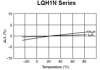
Inductor spec sheets have tolerance and temperature range, but I almost never see a temperature coefficient.

Does the combination of tolerance spec + temp range ~ imply Temp Coeff?

How do i determine temp coeff before procuring the parts.

I also see that capacitors are available as NTC and PTC - possibly to offset a change in L is some LC resonator. So why don't the L's also specify it ?
 

It's actually rarely specified, see below a curve for Murata LQH series as a counter-example.

3646864300_1417258094.png


Points to consider:
- aircore inductors (wirewound, thinfilm or metal-ceramic multilayer) have effectively very low T.C.
- ferrite core inductors have basically a relevant T.C., but it's often too complex (frequency and DC-current dependant, nonlinear or even nonmontonic over temperature) for an easy specification
- a T.C. specification isn't useful for inductors with large tolerances of 20% and more

To know the T.C. for a particular application though, it might be necessary to measure it yourself.
 

thanks chief. I know all this. And I have resigned myself to doing the TC measurements myself.

Despite the complexity of the dependence, one would think that at least the Mfgs would give SOME indication ! Is it 100ppm/ 500ppm/ 10,000ppm ?

On the other point - I am selecting +/- 5% inductors, AND which are stated as 'operable' between -55 to +105.

Now, does the 5% hold across the entire temperature range ? That is the critical fact which I am not sure about.

I would say it should, since that's whats written in the spec sheet. And if so, I can design with that, despite the fact that it most likely is not a linear dependency.
 
Last edited:

Reminds me a of a job I did some 40 years ago. I worked for a major communications firme who had delivered thousands of marine multiband communication receivers. The problem came to me as the coil for the BFO (IF frequency beat frequency oscillator) was wound with 39 SWG wire which was now unobtainable.
So I got the drawings out for the coil, and too my horror, found that it was a specially manufactured ferrite pot coil with an increased air gap in it, one presumes to give it a better temperature coefficient. So re-designing with a conventional core and 38 SWG wire. A, the oscillator worked over the required frequency range, and B, we put the oscillator in an oven and found that it performed perfectly over the desired temperature range.
So we wasted a lot of money over the previous production batches on the specially ground cores. The question still hangs over why 39 SWG wire? and we came to the conclusion that some wire rep. who wanted to sell the stuff had left a reel of in it the development laboratory, in the vain hope of it being incorporated into a design. I suppose we were in the end the only people using it, which would have been uneconomic, so it was discontinued.
Frank
 

Reminds me a of a job I did some 40 years ago..... Frank

Interesting anecdote Frank. So with that vast experience resource to draw from, can you guide me on my specific question ? About whether a spec of 5% and operating temp of xx to yy, does the 5% hold over the entire range ?
 

The temperature coefficient of an inductor depends on many things which may be additive or subtractive over a given temperature range. If you are building a LC oscillator, the temperature coefficient of the whole circuit can be offset by using a negative temperature coefficient of part of the C. If its for a filter, it is unlikely that the shift in the inductance would cause a measurable change in the filters characteristics and if there is a change it should be able to be compensated by the tuning of the filter. If the inductance is being used as a choke, then its value is non critical.
Another tale from the past:- A packset used a 1.75 MHZ reference crystal, the set was designed to work from -55 to +50 degrees C (NATO Spec.!). Over this range the crystal had to be +- 10 HZ, uncompensated it had a S shaped frequency/temperature curve, which was reduced from +- 150 HZ to less then the 10 HZ. This oscillator had THREE thermistors in series across the crystal, each with a different capacitor.
So it all depends on what you want. Precision inductors have to be manufactured to your specification.
Frank
 
Last edited:

The question could be more specific. You should mention an inductance range.
 

Thanks Chuckey/ Frank,

Here's the specsheet : https://www.bourns.com/data/global/pdfs/rl187_series.pdf

I'm interested in 1000uH in particular.

However I see now where the problem is - the +/-5% is marked only for 25degC ! So clearly the inductance could be anything else at other temperatures, and there's nothing in the sheets to say otherwise...

And yes - this is in a filter. Unfortunately its a Double-tuned BPF centered at 200Khz and BW of ~15Khz, so its quite critical.

Comments are very welcome.
 

Although ferrite, ceramics and copper have definite positive TempCo's but when rising pulsed DC current causes self-heating due to partial saturation , eddy current losses and copper PTC's, when load currents increase the result is a reduction in inductance which can cause a rise in current and losses that implies a large NTC.

Thus operating point for max load and surge loads has a greater bearing on NTC and thus is a more significant factor than the PTC tuned resonant frequency without DC.

There are at least two different methods for determining inductance and permeability and both are a function of actual magnetization curve and frequency. Compensation for such materials and devices is rarely reliable from vendor to vendor or even batch to batch unless specifically required and design for tuned circuits. 20% tolerance is common and 2% can be expensive.

If one is designing fixed frequency LC antenna then diodes are often used to tune the resonant frequency with DC controlled capacitance such as smart garage door openers. I recall the company that Delphi bought for its automotive smart garage door openers where one of over a hundred patents was on such a design so that it could work from -40 to + 40'C which I had thought was common knowledge.

AT cut Crystals on the other hand have a well known 3rd order S curve where the middle slope changes per fraction of a degree (minute) of the crystal cut . When a mil-temp 1PPM TCXO for $1 in BOM cost was required, none were avail at the time. So many special semi-automatic sorting tests were designed for sorting the crystal and varactor C1/12v ratio and the crystal S curve coefficients. But the production test had to be < 1 minute. I figured out an algorithm to generate the 3rd order S curve coefficients for TEMP vs F error over any range ( typically we bought +/-50ppm for $0.25 to reduce it to << 1ppm by VCXO DAC correction factors. The trick was to measure the ppm difference from 40'C to 70'C using a custom miniature SMT/ thermistor oven ( foam over copper FPC) that could test the component crystal case at these 2 temperatures in 15 seconds each and measure the ppm swing in a custom Xtal Test jig and thus be able to predict the 3rd order equation of error correction for the DAC + Varactor later put into flash memory. The result was that Xtals could be sorted into 10 bins which resulted in < 1 ppm error from -40 to +40C with no oven required. i.e. a TCXO or digitally tuned TCXO. Normally others spent long oven times to characterize these parameters and this was too costly. 1 ppm/yr aging was also corrected by the transceiver. This Temperature compensation was required for outdoor 2-way Automated Meter Reading.
XTAL Tempco.png
The point being, if you want to control it, you have to measure it and determine all the variables.
 

The Bourns inductors are specified as "RF chokes" and probably not suited for critical filter applications. Determining the actual temperature dependency is worth a try, though.

Precise low or medium frequency LC circuits used custom made inductors with ferrite pot core, like that described by chuckey in post #4.
 

However I see now where the problem is - the +/-5% is marked only for 25degC ! So clearly the inductance could be anything else at other temperatures, and there's nothing in the sheets to say otherwise...

Given that inductance is determined by the conductor geometry (small thermal expansion) and the ferrite core properties, I would look at TC of ferrite core materials.

Here's a data sheet of core materials:
**broken link removed**
 

Given that inductance is determined by the conductor geometry (small thermal expansion) and the ferrite core properties, I would look at TC of ferrite core materials.

Ferrite µr TC will be multiplied by a factor µr,eff/µr. µr,eff being the effective core permeability due to the air gap.
 

Another mobile Military device I worked on had a second IF of 250 KHZ and a B/W of 3 KHZ for SSB reception. The If strip which used 6(?) identical ferrite pot coils just used polystyrene capacitors as the resonant capacitor and there was no problem with temperature. The only problem was the asymmetrical bandwidth, due to different slopes of the + and - reactances from the centre frequencies. Long time ago now, but I believe that some of the circuits were resonated to 249 KHZ.
Frank
 

Although ferrite, ceramics and copper have definite positive TempCo's but when rising pulsed DC current causes self-heating.....
The point being, if you want to control it, you have to measure it and determine all the variables.
Thanks SunnySkyGuy. There's no DC in my circuit, so I am left with your fact that ferrites have a PTC. But how much ? Maybe your last quote is the only answer, and like i wrote before, there seems no short-cut for this project.

The Bourns inductors are specified as "RF chokes" and probably not suited for critical filter applications. Determining the actual temperature dependency is worth a try, though.

Precise low or medium frequency LC circuits used custom made inductors with ferrite pot core, like that described by chuckey in post #4.

Strange that an RF Choke is (1) being tested at sub 1-Mhz frequencies, and (2) coupled wth the fact that its a choke, why make them for 5% tolerances ? There's some disconnect here surely ?

I am still exploring the custom-built route, but there is very little expertise available locally.

Given that inductance is determined by the conductor geometry (small thermal expansion) and the ferrite core properties, I would look at TC of ferrite core materials.

Here's a data sheet of core materials:
**broken link removed**

Whew.. thanks Volker. Reading & trying to make sense of that doc will keep me quiet and off the air for a few months !!


Another mobile Military device I worked on had a second IF of 250 KHZ and a B/W of 3 KHZ for SSB reception. The If strip which used 6(?) identical ferrite pot coils just used polystyrene capacitors as the resonant capacitor and there was no problem with temperature. The only problem was the asymmetrical bandwidth, due to different slopes of the + and - reactances from the centre frequencies. Long time ago now, but I believe that some of the circuits were resonated to 249 KHZ.
Frank

Thats an interesting one Chuckey. Are you implying that the ferrites TC was somehow being offset by polystyrene caps ? From what I remember the poly caps were supposed to be very temperature stable..... or am i missing something ?
 

Yes and so were the inductors? To put it into perspective, 250 KHZ @ 1% = 2.5 KHZ, too much so I guess the Ls did not change by more then .05% over their working temperature, giving a B/W change of 125 HZ. Even this is too much for good speech, if the 125 HZ is chopped from the base end. The B/W of the speech, would go from 300 HZ - 3 KHZ, to 425HZ -3.125 KHZ, frequencies above 3 KHZ would not have been transmitted.
In general because of the flatness of a working (loaded) tuned circuit, I do not think there is a problem, The only problem may be if you are after very high attenuation close in to the nominal center frequency, i.e. -40 dB at Fc +- 3.5 KHZ, then because of the high Dattenuation/D frequency, some of the circuits might need to be precorrected to give a higher flank attenuation at Fc-3.5 KHZ.
Do a spread sheet with the likely components and see what the effect is.
Frank
 
Last edited:

..... so I guess the Ls did not change by more then .05% over their working temperature....
Frank

I think you got lucky there somehow. I guess it must have been something like the FTxx-61 mix which had a TC of 1000ppm. Even the -43 mix was below 1.25%.

but better than 0.05%... thats unbelievable. Why don't they make stuff like that anymore ?
 

Status
Not open for further replies.

Part and Inventory Search

Welcome to EDABoard.com

Sponsor

Back
Top