Continue to Site

Welcome to EDAboard.com

Welcome to our site! EDAboard.com is an international Electronics Discussion Forum focused on EDA software, circuits, schematics, books, theory, papers, asic, pld, 8051, DSP, Network, RF, Analog Design, PCB, Service Manuals... and a whole lot more! To participate you need to register. Registration is free. Click here to register now.

3-Phase Shunt type Motorcycle Regulator/Rectifier - Testing

Status
Not open for further replies.

abuhafss

Full Member level 2
Joined
Aug 8, 2010
Messages
136
Helped
1
Reputation
2
Reaction score
0
Trophy points
1,296
Activity points
2,346
Hi

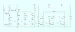
I made the circuit described here

**broken link removed**

Before installing it on the bike, I tested it with a variable power supply and a voltmeter:

Power Supply (+)ve clamped to Ign. Switch (i.e. the emitter of Q1)
Power Supply (-)ve clamped to Ground

Voltmeter (+)ve clamped to BATT (i.e. the cathodes of the rectifiers)
Voltmeter (-)ve clamped to Ground

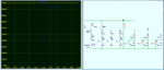
This set-up in LTSpice shows regulation at 15.1V (Power Supply) and about 650mV (Voltmeter). But when I tested physically, the voltmeter showed 0.54V from 8V onwards. D2 and R2 were getting hot! Surprisingly, D1 was at ambient temperature though both D1 and D2 are connected in series and same current would have been passing thru both. I replaced D2 with 1N4007 but same results.

I shall appreciate if anybody could help me resolve the issue and correct me to test the circuit.
 

Attachments

  • Screenshot 2014-11-27 22.36.04.png
    Screenshot 2014-11-27 22.36.04.png
    23.8 KB · Views: 126

If D2 got hot, then so should D1. Could it be that you miswired somewhere?

You should not get overheating of R1, zener, D1, D2, R2. I believe they only need a few mA. Their purpose is to turn on Q1 when battery V reaches 13 or 14 V.

I think you can increase R1 and R2. Try doubling both their values. Maybe even triple.
 

I seems like you did neither understand the regulator's operation principle nor tested it appropriately.

In operation the "switched Bat+" node is connected to the Bat+ node by the ignition switch and both have the same voltage. Vbat isn't allowed to raise to a voltage that high as in your test because the power source (the generator) is shorted before. To test the regulator operation, you would need a current limited AC source connected in place of the generator and a battery or a large filter capacitor replacing it.
 

No miswiring found.

I understand increasing the values of R1 and R2 with same ratio would give the same threshold voltage for Q1 base. But, the article mentions some "idle current" which should remain 0.013A

"R1, Z1, D1, D2, and R2 make up the detection circuit. R1 allows for an “idle” current to flow through the detection circuit so the Zener diode Z1 and regular diodes D1 and D2 are in the linear portion of their operating range. As the motorcycle’s electrical system-voltage increases past a set threshold, Q1 starts conducting. This sends current to the gates of the SCRs. D3-D5 act to isolate the gates from each other. R3, R5, and R7 act as current limiting resistors for the gates. R4, R6, and R8 act as drains for any possible leakage in Q1."

Choosing higher values for R1 and R2 will decrease the current but the circuit performs well with values like R1=470 and R2=560, I have checked in the simulator. Then what is that "idle current" for?
 

Please notice that in regulated operation, the current through the diodes and R2 won't exceed 15 mA. If the voltage raises above 14.1 - 14.5 V, the current increases and Z1 and R2 are dissipating some power.

If D1 or D2 getting hotter than Z1(D3), your circuit is definitely wrong.
 

I seems like you did neither understand the regulator's operation principle nor tested it appropriately.

In operation the "switched Bat+" node is connected to the Bat+ node by the ignition switch and both have the same voltage. Vbat isn't allowed to raise to a voltage that high as in your test because the power source (the generator) is shorted before. To test the regulator operation, you would need a current limited AC source connected in place of the generator and a battery or a large filter capacitor replacing it.

Yes, it is understood that in actual operation the "switch Bat+" is to be connected to battery's (+)ve terminal via ignition switch. And therefore, it gets connected to the (+)ve of the rectifiers.

In the simulator, I simply applied (0.5A) variable supply to the "switch Bat+" node just to see if the circuit regulates at the designed threshold. The voltage at rectifier's (+)ve i.e. V(bat) rises to about 650mV when threshold voltage is reached at the base of Q1. If the simulator shows that behavior, the physical test should also show something similar. Shouldn't it?

- - - Updated - - -

If D1 or D2 getting hotter than Z1(D3), your circuit is definitely wrong.

Agreed and for that reason I thoroughly checked my PCB (designed with Eagle software). When failed to trace anything abnormal, I started this thread. The strange thing is that only D2 is getting hot.
 

In the simulator, I simply applied (0.5A) variable supply to the "switch Bat+" node just to see if the circuit regulates at the designed threshold. The voltage at rectifier's (+)ve i.e. V(bat) rises to about 650mV when threshold voltage is reached at the base of Q1. If the simulator shows that behavior, the physical test should also show something similar. Shouldn't it?
The test hasn't much to do with normal operation. As said, there would be an AC source (the generator).
The voltage you see at the Bat+ node is probably some kind of SCR leakage current without practical impact. I won't expect that it's modelled correctly in the simulation.
 

Thanks for your input.
I'll get back shortly, after further thorough checking.
 

After thorough checking I found that Q1 was dude which I replaced and got the circuit working.

As for testing/checking the voltage regulator section, an LED + current limiting resistor (from a separate fixed power supply) connected to point A, B or C can indicate the regulation and also that the corresponding SCR is working. I have tested it with the current circuit and also another similar circuit.
 

Attachments

  • Screenshot 2014-12-02 01.42.46.png
    Screenshot 2014-12-02 01.42.46.png
    20.8 KB · Views: 100

Status
Not open for further replies.

Similar threads

Part and Inventory Search

Welcome to EDABoard.com

Sponsor

Back
Top