Continue to Site

Welcome to EDAboard.com

Welcome to our site! EDAboard.com is an international Electronics Discussion Forum focused on EDA software, circuits, schematics, books, theory, papers, asic, pld, 8051, DSP, Network, RF, Analog Design, PCB, Service Manuals... and a whole lot more! To participate you need to register. Registration is free. Click here to register now.

[SOLVED] Gasp Controller Asynchronous Pipeline went wrong

Status
Not open for further replies.

MZulkarnain Jaranee

Newbie level 5
Joined
Nov 27, 2014
Messages
8
Helped
0
Reputation
0
Reaction score
0
Trophy points
1
Activity points
70
Problem in Gasp Pipeline Controller in VHDL

Hi everyone,
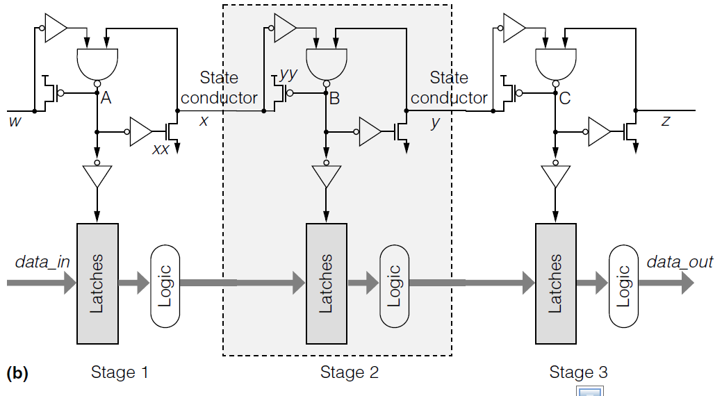
I'm working on the Gasp Controller as shown within the red area in the image attachment 111734. I did the code but the problem is the result didn't display as what show in the below image. Could anyone please advice/assist on this.

**broken link removed**

Here is the code
Code:
LIBRARY ieee;
USE ieee.std_logic_1164.all; 

LIBRARY work;

ENTITY gaspblock IS 
	PORT
	(
		x,y : inout STD_LOGIC;
		en : out STD_LOGIC;
		n_Out, p_out:  buffer  STD_LOGIC
	);
END gaspblock;

ARCHITECTURE bdf_type OF gaspblock IS 
	
	signal B, yy, a : std_LOGIC;
	
BEGIN 
	B <= ((not x) nand y);
	en <= not B;
	a <= not B;
	yy <= B;
	---- n- transistor ------
	process(a)
		
		begin
			case a is
			when '0' | 'L' => n_Out <= '1';
			when '1' | 'H' => n_Out <= '0';
			when others => n_Out <= 'X';
		end case;
	end process;   
	
	------ p -transistor ------
	process(yy)
		variable control: std_Logic;
		begin
			case yy is
			when '0' | 'L' => p_out <= '1';
			when '1' | 'H' => p_out <= '0';
			when others => p_out <= 'X';
		end case;
	end process;     
	
	x <= p_out;
	y <= n_Out;
	
END bdf_type;

Here is the netlist viewer result :

**broken link removed**

In the netlist viewer, the n_out, p_out and en all connected to input wire before y.
 
Last edited:

I can't see any attachments, but assigning 'X' looks like bug. 'Z' would be more useful.
"buffer" ports can cause trouble when you want to instantiate this entity.
I think it is better to use intermediate signals and normal "out" ports.

I don't understand what the code is supposed to do.
 
They are also wrongly using an inout for x and y primarily because they can "read" those values internal to the architecture.

This is an example of not understanding what the various port types are and why/when they are used. I think the OP should read the LRM or read a VHDL book.
 
Hi, actually I want to make a controller which will enable the latch.
As you can seen on my updated code below, the signal en will take the output from w AND x to enable the latch. After that, w and x will fetch the en. For example, initially, let say the w and x values start at 1, the en will become 1 and cause the latch to fetch data from data_in to data_out. After that, en will become the input of w and x and cause the latch to disable. However, the circuit didn't work when I tested it using university waveform program. The data_out didnt take the value of data_in. I can't figure out what is the problem still Im still new in VHDL. Hope you can assist/advice me on this :) Sorry for my bad english.

---------------------------------------------------------------------------------------------------------------
Code:
library ieee;
use ieee.std_logic_1164.all;
entity gasp_ctrl is
port(
	w,x : inout std_logic; --! bidirectional wire
	data_in : in std_logic; --! Data In when latch is enable
	data_out: out std_logic --
);
end gasp_ctrl;

architecture ctrl of gasp_ctrl is
	signal en, ww, xx : std_logic;
	
begin
	en <=  w and x; ------ 
	ww <= en;
	xx <= not en;
	w <= ww;
	x <= xx;

	
	-------- Latch ------
	process(en)
	begin
		if(en = '1') then
			data_out <= data_in;
		end if;
	end process;
end gasp_ctrl;
 

Can you draw a circuit diagram that has the correct functionality?
Maybe that can help us understand what you want to do.

Hi std_match,
The circuit is like this :
 

Attachments

  • gasp.jpg
    gasp.jpg
    182.6 KB · Views: 62

I think you're modeling that all wrong. VHDL isn't even a good switch level modeling tool, Verilog on the other hand has nmos and pmos switch modeling built in.

Seems to me this is a poor exercise they've given you and is pretty much useless for learning anything of value.

Regardless, you've got a problem with using inout, don't use it, period. inout is used for I/O pins on a IC package. i.e. buffers that are bidirectional and have tri-state or open drain outputs. That means multiple drivers can be placed on the net. FPGAs don't have internal tristate drivers, if you include them the tool has to convert them to multiplexers if it is capable of doing so.

The reason you aren't getting any simulation results is either the w x gate inputs are going X due to driving them externally (they are always driven internally by the architecture) and/or because you're simulation is likely to spin at time 0 until the iteration limit is reached due to the 0 delay assignments that feed back on themselves making a combinational loop that can't be evaluated to a stable state.

I suggest either using Verilog and model the switch transistors and the rest of the circuit and add delays to the model to emulate the switches and gate delays or run it in SPICE.

Hi Std_match and ads_ee,
thank you for your guidance.. Actually I'm doing my final year project whereby I want to compare mousetrap and gasp pipeline. For mousetrap, I got no issue since its simple, in other hand, Gasp pipeline really give me headache.
 

Pardon my ignorance, but what is "gasp" in the context of a gasp controller or gasp pipeline? I know what a gas pipeline is ;) and I know the gasp assembly preprocessor, but that's it.
 

Status
Not open for further replies.

Part and Inventory Search

Welcome to EDABoard.com

Sponsor

Back
Top