Continue to Site

Welcome to EDAboard.com

Welcome to our site! EDAboard.com is an international Electronics Discussion Forum focused on EDA software, circuits, schematics, books, theory, papers, asic, pld, 8051, DSP, Network, RF, Analog Design, PCB, Service Manuals... and a whole lot more! To participate you need to register. Registration is free. Click here to register now.

[SOLVED] Simple timer circuit needed NE555 with LEDs

Status
Not open for further replies.

tincan

Newbie level 5
Joined
Nov 26, 2014
Messages
9
Helped
0
Reputation
0
Reaction score
0
Trophy points
1
Activity points
59
Hello all,

there are quite a few topics on timers but I couldn't find the one that fits my project. I hope someone will provide a proper circuit diagram.

I have used NE555 before, but I do not know how to design circuits. Anyway, here's what I need:
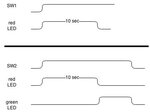
Unbenanntes Diagramm.jpg

I hope that explains it well, SW1 and SW2 will never be closed at the same time so it's actually two circuits I guess. I would like to operate it with 5V from USB Port.

Any help is much appreciated!
 

The first circuit can be built using 555 timer in monostable mode. The circuit is shown in the page https://www.555-timer-circuits.com/operating-modes.html
use it with R=91 kohm and C=100 uF (this will generate about 10 sec).
Note that the output time can be calculated form : Time Out Delay (secs) = 1.1 * R1 * C1 .

For the second circuit, the green LED delay time is not shown, so you can use two 555 timers in the monostable mode and you can choose the time you want. The output of the first timer will be an input for the second one,
 
  • Like
Reactions: tincan

    tincan

    Points: 2
    Helpful Answer Positive Rating
For low cost precision timers you can use a watch crystal on an HC4060 counter and get down to 1 Hz and use a decade counter and gate for each output state.
 

For the second circuit, the green LED delay time is not shown

Hello, thanks for the reply. In the second circuit the green LED should light up when the red goes out. Do I need two timers then? I will look at the link you provided.

@SunnySkyguy: Thanks, neither precision nor cost is a factor here.
 

If the green LED should light up -and still lighting- when the LED is off then one 555 timer is enough. So the circuit output should looks like:
**broken link removed**
And the RC values are the same as I said before.
But note that the green LED starts on. If you want it to start off then after red LED is off it lights up, then the circuit is different.

- - - Updated - - -

LED resistors could be any suitable value like 470 ohm.
 
  • Like
Reactions: tincan

    tincan

    Points: 2
    Helpful Answer Positive Rating
Hello, thanks for the reply. In the second circuit the green LED should light up when the red goes out. Do I need two timers then? I will look at the link you provided.

@SunnySkyguy: Thanks, neither precision nor cost is a factor here.

No problem.

SW1 looks like it is for 10 sec. False Start. ( Red Only)
SW2 looks like a GO after 10 sec and Off when SW2 is turned off.

Current limiting resistors can be on either side of LED to +5.

High bright Red LEDs are ~3V, Green ~3.5 and current limit is Ohm's Law on voltage drop from 5V. So 100 Ohms min for Red, 75 OHms min for Green for 20mA.
R for low intensity could be 470 Ohms or anything in between.

Not all 555's are the same but some indicate 10s requires 10uF & 1MOhm or similar CR product. i.e. 1uF x 10 MOhm

Not all 1uF caps are the same either and many do not support a time constant longer than 0.1s with 1~10uA of leakage, so a low leakage cap is required which costs more , plastic is best, but Tolerance is usually poor (20%)

Where you get your parts and which type will affect the results significantly.

- - - Updated - - -

If the green LED should light up -and still lighting- when the LED is off then one 555 timer is enough. So the circuit output should looks like:
**broken link removed**
And the RC values are the same as I said before.
But note that the green LED starts on. If you want it to start off then after red LED is off it lights up, then the circuit is different.

- - - Updated - - -

LED resistors could be any suitable value like 470 ohm.

Show him how to connect the 2 switches so they both go off.

Not all 555's use this time constant of 1.1 RC.
 

I have updated the signal chart. It is for a flight simulator landing gear lever:
gear indicator.jpg

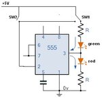
I have modified Eng.Fahd's circuit like this (pins 6,7,4,8 as before):
schematic.jpg


Many thanks for your effort!
 
Last edited by a moderator:

So I'm wondering, in the situation shown in my last post will the green LED be always on? I wouldn't want that.
 

Hi,
I have ordered some parts now. If anyone could answer the question wether the green LED will start OFF or how to do it - that would be great!
 

The following circuit do exactly what you showed in your new signal chart.
Sorry, I am so busy these days.
I forgot to put a resistor in the base of the transistor, so you could use a suitable resistor.

555timer.jpg
 
  • Like
Reactions: tincan

    tincan

    Points: 2
    Helpful Answer Positive Rating
That is more than I could ask for. Thank you so much.
 

I have a problem now. After some reading I found out why it is not working as expected. The timer obviously needs short pulses to ground in order to work correctly. The switches I have to use are on or off. Is there a fix for this?
 

Yes, the timer needs short pulses to ground as I showed in the schematic. These switches are on or off! I did not understand what is your problem?
What is the kind of your switches?
 

Hello,
I have a microswitch that is either in closed or open state. The gear lever will push it permanently when in position. However, I will make a mechanical solution to this small problem.
 

Status
Not open for further replies.

Part and Inventory Search

Welcome to EDABoard.com

Sponsor

Back
Top