Bushmenass
Newbie level 2
Hello everybody,
At first, I'm just a recent graduate of telecommunications and electronics engineering and have little real life experience, especially with RF equipment...
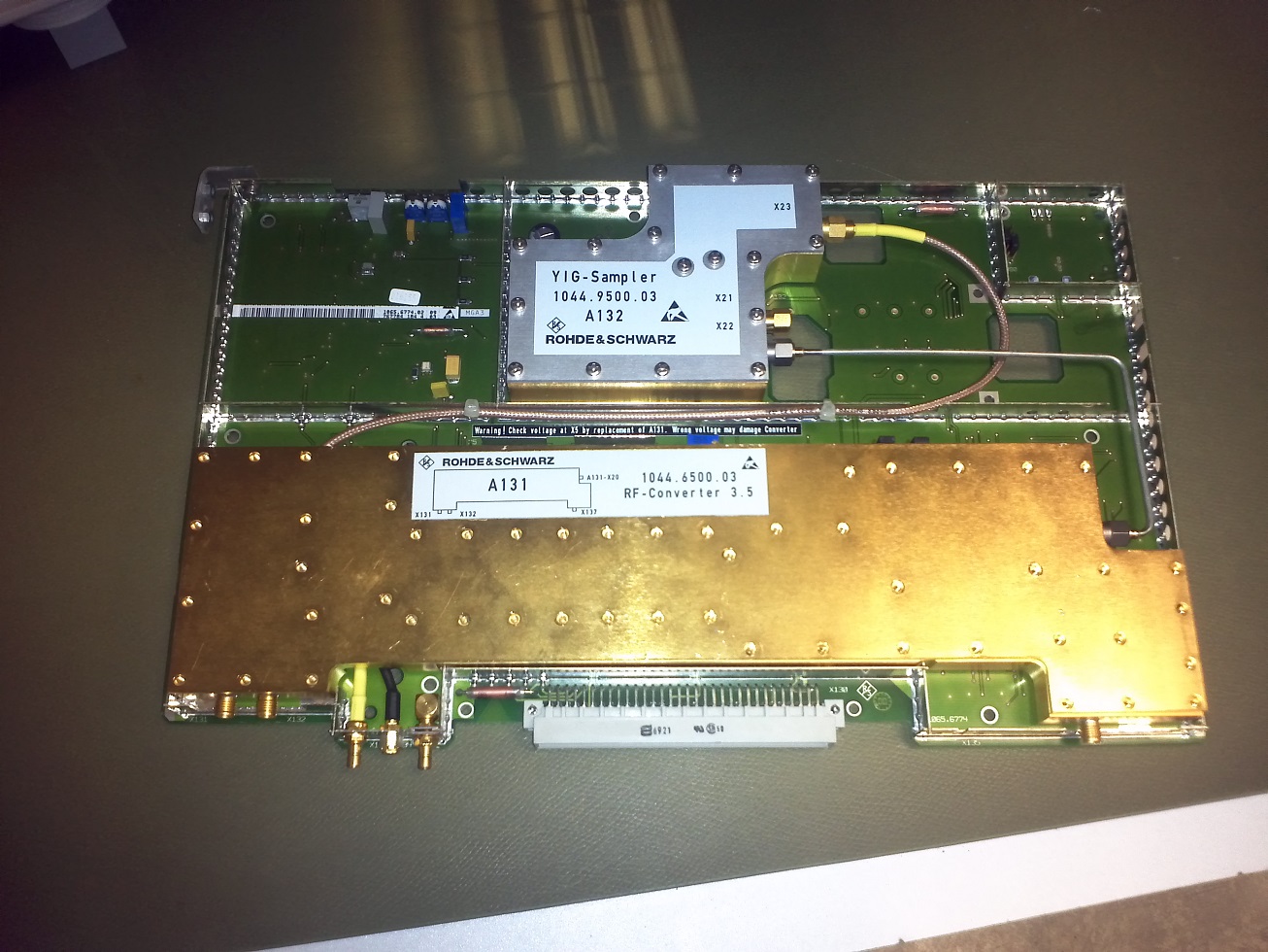
I have a Rohde&Schwarz FSEA30 spectrum analyser, that was failing self-test by stating an RF-converter fault. Since the part would cost as much as a new analyzer, I was trying to detect the problem myself. Tons of googling lead to the idea of "frontend mixer" burning out due to excesive power at the input, and I think this is actually the problem in this particular case...
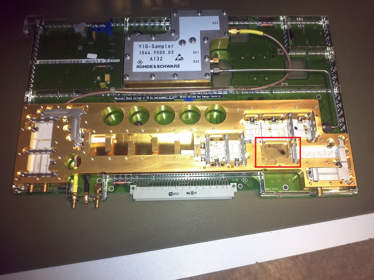
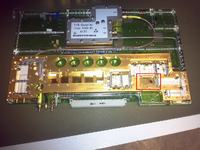
The thing is, that most of the time spectrum analysers have the frontend mixer as a separate unit, but this one (if I understand correctly) has it embedded in one big metal case together with further ~"RF conversion hardware" (see pictures).
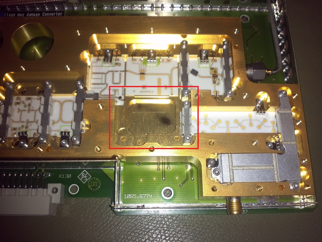
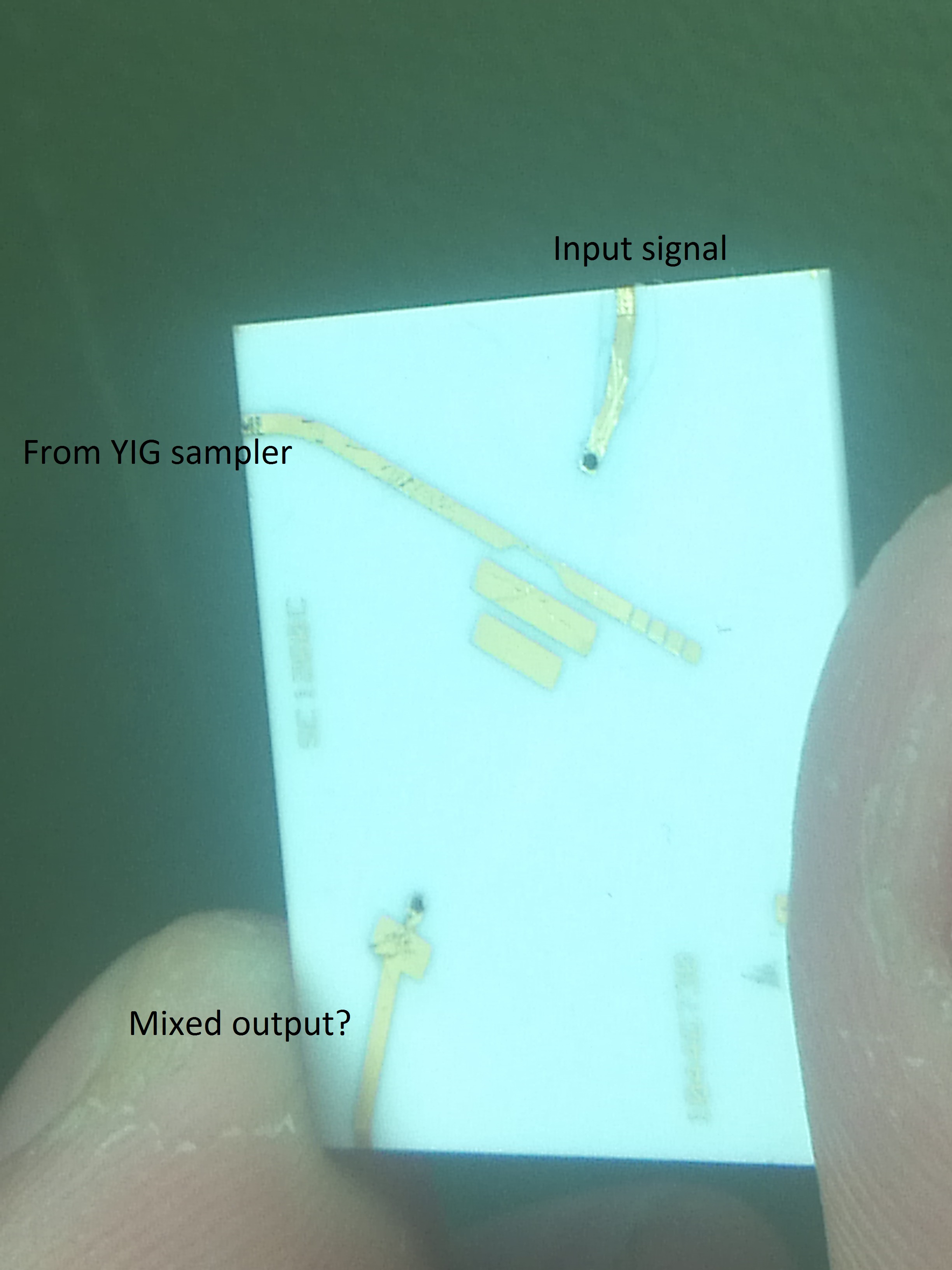
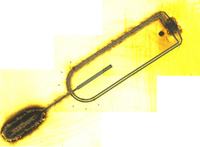
I found a burned piece of pcb that looks like it is some kind of an "inductive mixing pcb circuit"?? It does not have any kind of active or passive smd elements, just a copper tracing and some tiny wire bonding.
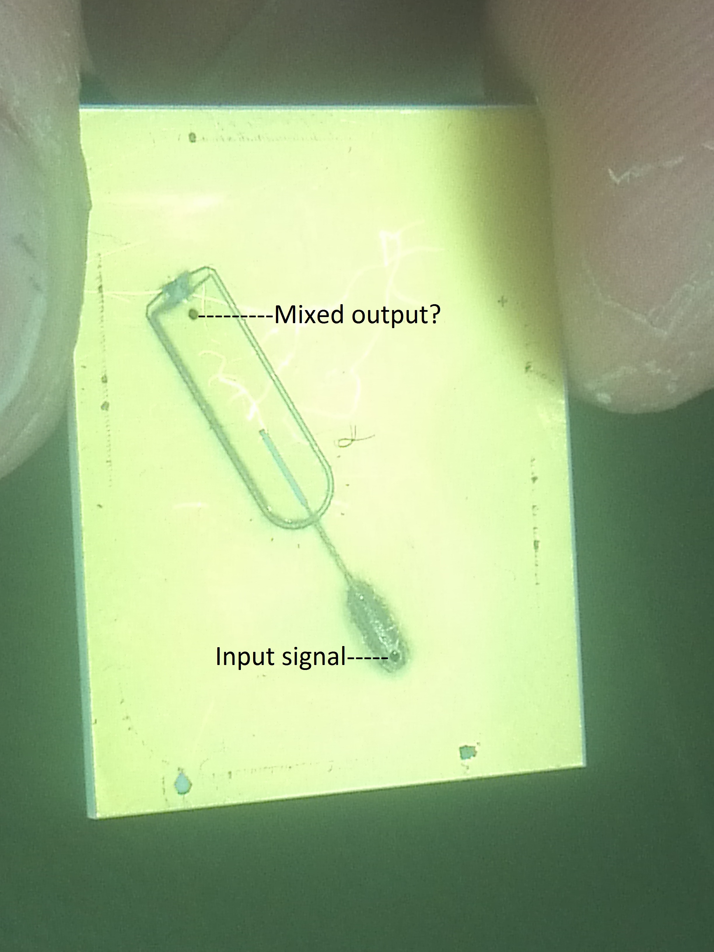
Having hopes that this is the only problem and the further active elements was not damaged, I would like to try to replicate this small piece of pcb, but I have no knowledge of how this thing should be actually working, how to bond these parts of tracing together (apparently they were)... If you could share any general knowledge about RF signal mixing hardware I might be working in a bit closer circuit of uncertainty.
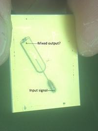
There is a photo made with a digital microscope and some more photos. I can see the approximate shape of a burned out tracing, but should the input signal be DC bonded to the output? Or should the output be just some kind of induction of both signals, etc..? Any suggestions are greatly appreciated.


At first, I'm just a recent graduate of telecommunications and electronics engineering and have little real life experience, especially with RF equipment...
I have a Rohde&Schwarz FSEA30 spectrum analyser, that was failing self-test by stating an RF-converter fault. Since the part would cost as much as a new analyzer, I was trying to detect the problem myself. Tons of googling lead to the idea of "frontend mixer" burning out due to excesive power at the input, and I think this is actually the problem in this particular case...
The thing is, that most of the time spectrum analysers have the frontend mixer as a separate unit, but this one (if I understand correctly) has it embedded in one big metal case together with further ~"RF conversion hardware" (see pictures).
I found a burned piece of pcb that looks like it is some kind of an "inductive mixing pcb circuit"?? It does not have any kind of active or passive smd elements, just a copper tracing and some tiny wire bonding.
Having hopes that this is the only problem and the further active elements was not damaged, I would like to try to replicate this small piece of pcb, but I have no knowledge of how this thing should be actually working, how to bond these parts of tracing together (apparently they were)... If you could share any general knowledge about RF signal mixing hardware I might be working in a bit closer circuit of uncertainty.
There is a photo made with a digital microscope and some more photos. I can see the approximate shape of a burned out tracing, but should the input signal be DC bonded to the output? Or should the output be just some kind of induction of both signals, etc..? Any suggestions are greatly appreciated.