Continue to Site

Welcome to EDAboard.com

Welcome to our site! EDAboard.com is an international Electronics Discussion Forum focused on EDA software, circuits, schematics, books, theory, papers, asic, pld, 8051, DSP, Network, RF, Analog Design, PCB, Service Manuals... and a whole lot more! To participate you need to register. Registration is free. Click here to register now.

[SOLVED] Pure sinewave inverter with toroidal transformer

Status
Not open for further replies.
R

red_alert

Guest
Hi guys,

I've just built a pure sinewave inverter (230V / 3kW) with a LF output transformer but I want to change the regular (EI) transformer with a real(!) one - a high efficiency toroidal type.

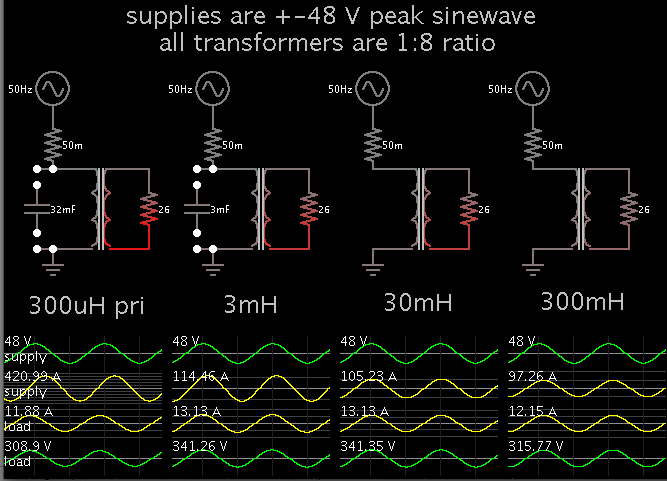
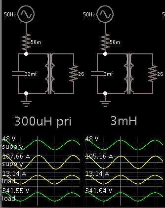
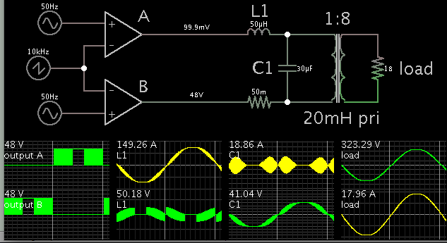
But here comes the problem: the traditional inverter design use the output LF transformer leakage inductance as a "natural" filter for the SPWM high frequency band.

The toroidal transformer has a very low leakage inductance so I have to design a separate filter between the H-bridge output and toroidal transformer input (30V AC, being used with a 48V DC solar system).

The (s)PWM frequency it's about 10 kHz. The H-bridge max output current will be 75 A. How to properly design a filter for this situation? It has to be a LC filter (with C parallel mounted on the transformer input)?

Like I said before, the actual design uses the transformer's leakage inductance and a parallel capacitor (2.2 uF) across the transformer output (230V).

Another problem I've encountered is the toroidal transformer inrush current at startup so I
have to find a way to limit it. Being a high current (>100A) I couldn't use NTC resitors and I want to avoid using relays (to shunt an inline high-watt resistor) too.

I guess the solution is to design a software soft-start.. so it means I have to generate a progresivelly increasing amplitude of the SPWM sinewave, during one second or so at startup? Do I have to disconnect the load (230V) during this startup sequence?

Thank you in advance for any tips.
 

The (s)PWM frequency it's about 10 kHz. The H-bridge max output current will be 75 A. How to properly design a filter for this situation? It has to be a LC filter (with C parallel mounted on the transformer input)?

Sinewave inverters are a popular topic here. You can get some hints by looking through the similar threads listed at the bottom of this column.

Question: Between 75A pulses, do you shut off all current through the primary, or do you allow a way for current to flow through it at low impedance?

If it is the latter, you may only need an additional series inductor, to obtain a relatively clean sinewave.

However if you cause the primary to see high impedance between pulses, then you can expect to add a capacitor or two, in addition to an inductor. In other words, more design work.
 
Hi,

Compared with EI transformers toroidal transformers have a very hard saturation bahaviour.
The rise in current is very high when saturated.

Any DC component at the transformer's input will give you problems.
Either you can avoid DC by design (serial capacitor for example) or expect you need other saturation protection circuitry.

Klaus
 

Your problem is very easy ,if your have a micro metal toroidal core just put it in series to the toroidal transformer is you see in the picture I depict here
 

Question: Between 75A pulses, do you shut off all current through the primary, or do you allow a way for current to flow through it at low impedance?

BradtheRad: Between 75A pulses, I put both low side MOSFETs to ground. Is that the low impedance path you did mention?

However if you cause the primary to see high impedance between pulses, then you can expect to add a capacitor or two, in addition to an inductor.

Where to put that capacitor? Across the primary (low voltage) or across the secondary (as in traditional design)? Honestly, I prefer to clean the sinewave before reaching the LF transformer (it's a "low frequency" device, after all).

Either you can avoid DC by design (serial capacitor for example) or expect you need other saturation protection circuitry.

Klauss: Can you tell me more about other saturation protection methods?? How to test if the transformer works in the saturation region?

Your problem is very easy ,if your have a micro metal toroidal core just put it in series to the toroidal transformer is you see in the picture I depict here

Munirali28: I guess it's what I've been thinking of (and read about it). Can you post the image, please? Do you know how to properly calculate the inductance value? I've just bought some micrometal toroidal inductors (50A / 68uH) to test some series/parallel combinations. Do I need a capacitor across the primary (30V) too?

I would use a switching frequency of at least 20 Khz, to avoid listening the transformer's and inductors whining.

schmitt trigger: Actually, I've just ordered a 4 kW toroidal transformer (to upgrade my design) so it will be a pretty hard work to switch that amount of current. I might put it on the risk trying to switch those MOSFETs quicker than that (10 kHz). I've read about using 5-10 kHz for this amount of switched power. I could live with that "whine" for now! ;)
 

There is no specific formular for calculating micro metal toroids because they change appreciably with temperature and frequency,but there are digital meters designed for measuring the inductance at various conditions.
 

BradtheRad: Between 75A pulses, I put both low side MOSFETs to ground. Is that the low impedance path you did mention?

Erratum:

I was trying to say that I put both low side SWITCHES to ground (in the interval between 75A pulses).. that's it, I drive both low side MOSFETs in ON (conducting) state. Sorry for the previous poor explanation.

Munirali28:

I already have a calculation tool for toroid inductors.. I just want to know how to calculate/choose the right value of that inductance in this particular case (PWM frequency, switched power).
 

I was trying to say that I put both low side SWITCHES to ground (in the interval between 75A pulses).. that's it, I drive both low side MOSFETs in ON (conducting) state. Sorry for the previous poor explanation.

This simulation shows what I understand about how to smooth the SPWM waveform. The values were adjusted to work with your parameters.

Two op amps mimic a full H-bridge, generating SPWM AC for the transformer. The carrier is 1.5 KHz. The fundamental is 50 Hz.

The op amps provide a path to ground during the part of the cycle when they are not outputting SPWM. As a result, the primary loop is always allowed to conduct. It is never at high impedance.

To smooth (choke) the SPWM, a plain 200 uH coil is sufficient (for my 1.5 kHz carrier and amperage). For your 10 kHz carrier, you can use a smaller value.

**broken link removed**

For the primary I picked 1mH, a small-ish value. I chose it by running another simulation where 50 Hz sinewaves are sent to a 1:8 step-up transformer, to a 3 kW load. The primary values range from 300 uH to 300 mH. The 300 uH needs power factor correction because it admits hundreds of amperes. To bring this down to a reasonable amount, it needs 30,000 microFarads across it.

The 1 mH needs only 10,000 microFarads of pfc.

Hope this helps.
 

    V

    Points: 2
    Helpful Answer Positive Rating
Before you decide on any design change. define what level of protection to the unit, equipment, environment and personnel is most important and mandatory.
1. Input or output disturbance of any kind.
2. Detection, protection and recovery of fault condition.
3. EMI from discontinuous input or output current pulses.
4. Protection from over thermal, magnetic, current or voltage mis-wiring or ground fault.
 

BradtheRad:

Thank you very much for the simulation! I just need to be sure: when we're talking about transformer's "primary" are we talking about the low voltage (30 V) one, right? (being a step-up transformer)

So.. shall I put a 10 000 uF capacitor across this primary winding? Isn't way too much? Doesn't it affect the fundamental (50 Hz) too? Or did I misunderstand something? The 50-100 uH toroidal choke looks ok though.

SunnySkyguy:

I've designed and built this inverter for personal use (for offgrid living) so I have only provided basic protections (overvoltages, overecurrent) as I'm the only "user". The input is a large batteries bank - so no major disturbances here.
 

Avoid putting a large capacitor at the output of the inverter ,because it will overload the inverter after filtering effect
 

BradtheRad:

Thank you very much for the simulation! I just need to be sure: when we're talking about transformer's "primary" are we talking about the low voltage (30 V) one, right? (being a step-up transformer)

So.. shall I put a 10 000 uF capacitor across this primary winding? Isn't way too much? Doesn't it affect the fundamental (50 Hz) too? Or did I misunderstand something? The 50-100 uH toroidal choke looks ok though.

This is the simulation I ran to explore the effect of changing the inductance of the primary. It reveals the need for power factor correction. Capacitors are used for this purpose.

I use a 50 Hz sinewave since that is what you want going through your transformer.


The smallest value is at left. It is inefficient. A 32mF capacitor will cure its power factor problem. Its power factor is low because:
(a) The supply voltage waveform does not align with the ampere waveform.
(b) It has to draw enormous current from the supply.
(c) The load receives mediocre voltage and current.

Notice the middle two circuits. They are the most efficient, for reasons: (a) They draw a reasonable amount of amperes from the supply.
(b) The load gets both the greatest voltage and the greatest amperes.

Notice the supply waveforms of the three right-hand circuits. The voltage waveform is more or less aligned with the current waveform. They do not need pfc quite as much.

- - - Updated - - -

Here are the first two circuits, after connecting pfc capacitors.

9980682100_1416091147.png


Efficiency is improved.

Ampere draw is less.

The supply waveforms (V and A) coincide.

The load receives full voltage and full current. Right up there with the performance of the 30 mH primary.

If your primary is over 10 mH then you probably don't need a pfc capacitor.

If your primary is 1 mH then a pfc cap of 10,000 uF is needed, theoretically.
 

    V

    Points: 2
    Helpful Answer Positive Rating
You may as well filter the o/p of the transformer as this allows for lower current chokes (higher L) and smaller values of C (630VDC), there will be some extra heating in the TX due to the filter currents and due to the square wave input causing extra core losses - but the chokes are so much easier.
Usually you calc the filter L & C to give only a 10-20% increase in current fundamental - that flows in the filter C, so bigger L and smaller C achieves this - however the dynamic response to a step load with a large L means that the PWM has to change more and needs more overhead (higher source volts) than for smaller filter L.
We all look forward to the results regardless of the approach you adopt.
Regarding net average DC applied to the LV primary, if the primary is 1milli-ohm and the net average DC volts applied are 10mV (due to asymmetry of drive or mosfet mismatch) then you will have a real net average 10 amps DC flowing in the Tx primary (and mosfets), only an amp or less is needed to saturate the Tx core on a toroid -and cause real problems (big rises in magnetising current) - usually some type of peak current control is used to keep this under control or measure the net DC and move the PWM bias to compensate - we have used the latter approach on 3kW grid tied inverters to keep the net output DC current to <5mA.
Hope this helps...
 
  • Like
Reactions: Orson Cart

    Orson Cart

    Points: 2
    Helpful Answer Positive Rating
    V

    Points: 2
    Helpful Answer Positive Rating
Loads of very helpful informations.. thank you very much!

I don't have the transformer for the moment (will arrive in few days) so I can't make any experiments yet. I also ordered some 47 uH (50 Amps) toroidal chokes and already have lots of low rds(on) electrolytic capacitors and high current pulse capacitors (polypropylene).

I'll try all the combinations you suggest - I just want to be sure I won't blow the MOSFETS (as they cost me a fortune!).

So a low pass input filter with a cut off frequency of 400-500 Hz will do the job? As it's 10 times bigger than fundamental (50Hz) and 20 times smaller than the carrier (10 kHz)?

I don't mind using as many/large chokes as it needed and any other kind of components just to get the best results (this inverter will feed my entire home).

I've read about some similar inverter modifications and those guys only put a toroidal choke inductor (100 uH) in series with transformer primary (low voltage) and some similar chokes (on ETD ferrite core) on each output branches - and maybe a small capacitor too, across the transformer output (high voltage).

But that was more like an empirical experiment so that's why I asked for (professional) help, to really understand how to properly calculate those circuits.
 

If your primary is over 10 mH then you probably don't need a pfc capacitor.

BradtheRad:

I've just found out that the toroidal transformer has a primary (low voltage) impedance of 20-25 mH; so I won't need a PFC capacitor? Also, the leakage inductance is ~ 3 uH. Does it help calculate the choke inductance? Thank you very much for your help.
 

BradtheRad:

I've just found out that the toroidal transformer has a primary (low voltage) impedance of 20-25 mH; so I won't need a PFC capacitor? Also, the leakage inductance is ~ 3 uH. Does it help calculate the choke inductance? Thank you very much for your help.

Right, it looks like the manufacturer designed it to perform in the most efficient range (between the 3mH and 30mH in my post #13).

With a carrier at 10kHz, you should get a smooth sine with a choke coil of tens of uH.

You still need a capacitor across the primary. A few tens of uF. This is partly for filtering, partly for pfc.

So a low pass input filter with a cut off frequency of 400-500 Hz will do the job? As it's 10 times bigger than fundamental (50Hz) and 20 times smaller than the carrier (10 kHz)?

Yes, although you need to check calculations for various loads. The L and C values will depend on the load.

Going back to the simulation in post #9, with revised values.

Carrier 10 kHz.

Load was re-adjusted to draw 3 kW nominal. (230V x 13A = 3000W.) Current needs to peak at 18A.


The L1 and C1 values were chosen a bit undersize, to show how it looks when they just about do the filtering job.

With lighter load, you may want to increase L1. It may be difficult to settle on a single value.
 

    V

    Points: 2
    Helpful Answer Positive Rating
BradtheRad:

Thanks for all your effort, now it's all clear. I just can't wait to test it.


I have another question though. How to avoid the strong inrush current at startup, generated by the toroidal transformer?


(1) Is it enough/feasible to generate a progressive increased output voltage (using the sPWM signal)?

(2) How long this interval should be? (to increase the output voltage from zero(?) to 230 V)?

(3) Do I have to disconnect the load during this step?


Thanks again for any help.
 

How to avoid the strong inrush current at startup, generated by the toroidal transformer?

(1) Is it enough/feasible to generate a progressive increased output voltage (using the sPWM signal)?

(2) How long this interval should be? (to increase the output voltage from zero(?) to 230 V)?

Gradual startup is similar to starting the SPWM from the very beginning of a cycle. It sends a few narrow pulses at first. From what the simulation shows, you have normal operation in the first cycle. (However as we know, simulators are not infallible.)

On the other hand, if you start the SPWM at the 90 or 270 degree mark, then you expose all components to peak current abruptly.

(3) Do I have to disconnect the load during this step?

With no load connected, the secondary voltage soars. Then when you connect the load, it is exposed to overvoltage.

Perhaps this can be handled by the same voltage regulation which adjusts voltage to the load in normal operation.

Transformers have a dozen parameters making them act the way they act, so a simulator is liable to miss some aspects of their behavior, especially transient behavior.

-----------------------------------

Now that the component values are falling into place...

I recall that Falstad's is able to export a link (below) containing an entire simulation. Clicking it will:

a) open the website www.falstad.com/circuit.
b) load my schematic into the simulator. (Click Allow to load the Java applet.)
c) and run it on your computer.


You'll see an animated, interactive simulation. Electrons (or rather, current bundles) flow through wires, depicting direction and intensity.

You can change values easily by right-clicking on a component and select Edit. Results are immediate.

Since you built the real deal, you'll quickly know more than I know about its operation.
 

Gradual startup is similar to starting the SPWM from the very beginning of a cycle. It sends a few narrow pulses at first. From what the simulation shows, you have normal operation in the first cycle.

So do you think one cycle is enough? I was thinking of starting with a 5% amplitude (sPWM ratio) then increasing it cycle by cycle with a 2% ratio, so after almost 50 cycles (one second) I have full (230 V) output voltage. Anyway, I could play with it as long it will stay in the safe zone.

(I'll try the Falstad simulation later - no java on my current machine)
 

Status
Not open for further replies.

Similar threads

Part and Inventory Search

Welcome to EDABoard.com

Sponsor

Back
Top