Continue to Site

Welcome to EDAboard.com

Welcome to our site! EDAboard.com is an international Electronics Discussion Forum focused on EDA software, circuits, schematics, books, theory, papers, asic, pld, 8051, DSP, Network, RF, Analog Design, PCB, Service Manuals... and a whole lot more! To participate you need to register. Registration is free. Click here to register now.

Mirco UHF hearing AID Circuit.

Status
Not open for further replies.

illusionists

Junior Member level 2
Joined
Nov 10, 2014
Messages
22
Helped
0
Reputation
0
Reaction score
0
Trophy points
1
Activity points
188
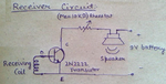
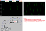
As we know that there exist UHF earpiece by Chinese companies. The working principle is simple. Receive electromagnetic waves from an loop. We the receiver consist of T-Coil (Telecoil) .
i works on single 1.5 volts (sound not much clear) .But works. I had bought it an broke while reversing the circuit :p . small smd. but there were 3 resistors,2 diodes, and 2 transistor. // If we want we can use 3 volts .
So ,guru's,how can we make one ? what parts we need ? what op-amp IC . Circuit? .Please share. If i complete then i share whole nice youtube tutorial on how to make it from base. I'm not that good in electronics (I'm from IT) .But electronics had been interesting me from some time and years.
See here is an example:-
super-sneak-hidden-in-ear-spy-audio-receiver[1].jpg

Oh,and one i bought was same as above and it also had an telecoil .
Respect "Audioguru"
 

I do not make hearing aids. Please look for a suitable circuit yourself. Its IC will probably not be available in your country anyway.

I have never heard of a "UHF" hearing aid. UHF is an Ultra-High-Frequency, a radio or TV signal. Maybe in your country they have a very high power UHF radio transmitter and the hearing aids are simple crystal radios. In my country a concert hall or theater will have a loop of wire around it driven from a high power audio amplifier. The hearing aids have a coil of wire inside that picks up the induced signal or from the signal induced from a magnetic telephone.

I simulated the extremely but horrible circuit linked in your personal messages to me. It is terrible with DC in the earpiece, very high clipping distortion because it is biased wrongly and it has a low maximum output level and gain. I corrected its biasing but since it does not have enough gain and not enough negative feedback then it is still very distorted. With a 3V supply its maximum output level and gain are 3 times higher but still are too low to be a hearing aid.

Your idea of using an old LM386 amplifier with high gain needs a minimum of 4V for its supply (a 6V battery drops to 4V during its life) and it produces a lot of hiss noise. Its SMD package is too big for a hearing aid that is in your ear canal.
 

Attachments

  • bad hearing aid.png
    bad hearing aid.png
    26.3 KB · Views: 163
  • bad hearing aid re-biased.png
    bad hearing aid re-biased.png
    27.8 KB · Views: 433
Nice and agreed. With all that said I'm losing hopes :<.

Actually earpiece is the receiver in our case, it is surely consisting of T-Coil .

You got some mod or circuit which we can use as earpiece? We need tcoil one, not MIC one.

Also, we are not concerned about audio quality like stereo or mono. If we normal person can here then it floats our boat. I guess by default it will be stereo in nature.

But all this winds up to same question, where to get an tcoil receiver circuit. All the way confused, srsly :< :<

Also, not necessary that we must use any audio op-amp for our earpiece since normal person is not deaf. So how we going to approach on this receiver!
 
Last edited by a moderator:

it is simply an inductor that a normal hearing aid uses to pickup inductive signals. <-for sure.

Well im not against opamp for receiver, but if its components are too big then no point using.Also earpiece will be for normal person lik u me or any other, except deaf guys. Deaf guy's must surely use good quality aid.
 

Stereo or mono has NOTHING to do with audio quality, but stereo (two separate earphone channels) cancels echoes in a room which is important for a hearing aid.
Go into a reverberant room then plug one ear when someone is talking to you. You will hear many echoes.

Good audio has a flat frequency response from 20Hz to 20kHz, very low distortion and very low noise.

I do not know if your "tcoil" is a UHF resonant tuned LC used in a simple radio receiver or if it is simply an inductor that a normal hearing aid uses to pickup inductive signals.

Why don't you want to use an audio opamp that has low noise and low distortion to drive a low gain power amplifier?

- - - Updated - - -

Please STOP sending personal messages to me about this project.

Here is my simulation of the horrible Hearing Aid With Push Pull Output from Talking Electronics.
Its output level is too low for a hearing aid (and drops more as its battery voltage runs down) and it has severe distortion.
 

Attachments

  • hearing aid with push pull output.png
    hearing aid with push pull output.png
    29.6 KB · Views: 417
Oh,ok. Can you or anyone mod this to be an better circuit ? Not best but must work normally.With low battery drain and good gain and low distortion.

Any gurus?
 
Last edited:

I have designed many excellent audio amplifiers.
They do not have low battery drain since they must drive a transducer (speaker) with enough power to fill a room.
They have as much gain as is needed.
They have very low noise (hiss) and very low distortion.

If I were to design a hearing aid then I would use one of the new amplifier ICs from Texas Instruments. They are digital so they have low battery drain.

I received ANOTHER personal message. In it is the design of a hearing aid amplifier from an Electronics Engineer University Professor in India. Its input signal generator is supposed to be a coil of wire. I show in a simulation that since the base of the transistor is not biased then its output is missing much of the signal and is extremely distorted.
 

Attachments

  • simple hearing aid1.png
    simple hearing aid1.png
    468.7 KB · Views: 156
  • simple hearing aid2.png
    simple hearing aid2.png
    39.9 KB · Views: 178
I see.
NOW with all that said, you got an better circuit or near to one. Can you make circuit a bit better!!
Getting disappointed :<

Edit:
Just got an warning to ask via PM. Ok will ask only via thread. :(
 
Last edited:

Texas Instruments is probably the largest semiconductor manufacturer in the world because last year they bought National Semiconductor company.
They list 25 headphones stereo amplifier ICs. I selected one (LM4911) that works from a battery as low as 2V so a 3V Lithium coin cell battery is fine.
The LM4911 is fairly small, has low noise, has low distortion and provides 40mW per channel into 16 ohms with a 3V supply.
It can be driven from a stereo preamplifier IC.
In North America a free sample is available.

They have many digital amplifier ICs that use low battery current but they are so small that a robot is needed to make the connections.
 

Attachments

  • LM4911.png
    LM4911.png
    137.2 KB · Views: 162
Oh great, now we get an start. Thanks for the effort and to bear with me @ 'Audioguru'.

Now on mobile, mid night. Tomorrow will find an decent circuit for that IC and post here.
Hey Audioguru,before bed, want to say you thanks. Cya

- - - Updated - - -

Being an alien's fan and ufo loving guy, I see / saw many documentary' s. And I very wel know about texas instruments (giant of electronics market). Tx instruments has just been trying to reverse ufo technology step by step. The big whistle blower 'Boyd Bushman' had worked in Tx instruments. Sadly he passed away couple months back. Gov black projects are mainly done by 'lockheat Martin' , which has an internal tie up with Tx instruments. Lots to say n disclose, but here I don't want an offtopic attention.
 

Compared to LM4911 ,what is your thoughts on this ? https://www.ti.com/product/tpa6100a2

Is TPA6100A2 better than LM4911 ?
Also this can work on 1.6-V - 3.6V,whereas LM4911 works on 2V - 5.5V .

which is better for tiny earpiece, LM4911 or TPA6100A2 ?
 

which is better for tiny earpiece, LM4911 or TPA6100A2 ?
Both amplifier ICs are almost the same. The LM4911 was designed by National Semi and the TPA6100 was designed by Texas Instruments.

The datasheet for the TPA6100 describes that the maximum output power drops when the supply voltage is low so it might not be loud enough.
The Applications Note describes what I have been saying about the horrible circuits you posted that have DC in the earphones, "Connecting the headphone directly to the amplifier output without any capacitor in the path would likely damage the headphone due to dc current flow through the voice coil. Therefore, a coupling capacitor is required to block the dc offset voltage from reaching the load." But in the horrible circuits the output transistor does not work without having a load.

Are the amplifier ICs available in your country?
 
I must admit, you are too good in electronics as well as explanation. I got the concept you said about supply voltage fall and output sound fall stuff. Amazing. Also agree on that capacitor need.

Well I also know some rumors that other companies copy the texas IC and change few stuff in datasheet.

As for the availability, I'm planning to order one or more via DHL .

Also, I'm bit skeptic about reading the data sheet circuit. I mean, there's no components value provided. Nor and proper readable circuit diagram. Maybe its there but I can't figure it out. Again my lack in electronics tends to be an barrier. But on same hand I'm Damnn too much desperate to making an working one .

Can you attach the circuit with simplicity, an keep in mind we are going with SMT and it wil be made to fit in ear.So only required components are to be counted. But I must admit, electronic is not easy as I thought. ;p

Respect, Audioguru

- - - Updated - - -

Not Headphones, we will use this tiny speaker which is used in that tiny earpiece. http://m.aliexpress.com/item/1858270796.html
 

Given your evident complete lack of electronics knowhow (The TPA6100, while the wrong thing for the job, does actually have the calcs on the datasheet for required component values), might I suggest just buying the things in ( https://www.canford.co.uk/CANFORD-WIRELESS-EARPHONES for an example), or failing that buying an amplified speaker so at least you do not have to worry about the power amp?

Knoles ES-23127-000 spings to mind as suitable and has an on board class D power amp.

Now before the power stage you will need a preamp and some pretty severe filtering to keep the power frequency interference out of the thing, together with a hell of a lot of really fine wire forming the pickup coil, and no I am not going to design that for you.

Anything you design to fit in that form factor will require automated assembly, you are looking at circuits using 0201 or smaller components, and really fine pitch ball or DFN package semiconductors these are not solderable by hand (For most of us, I have a production guy who would try...).

Do you have the acoustics and mechanical design skills to couple that transducer to the ear canal, and the measurement kit to measure your coupling?

'T' setting on hearing aids by the way receves what is often referred to as AFILS (Audio frequency Induction Loop).

Good luck, but seriously I would buy it in.
 
The 2014 Knowles website does not list the hearing aid speaker you found in China so maybe it will be an old obsolete one. maybe it is a cheap Chinese copy.

The datasheets for Knowles balanced armature transducers show a horrible frequency response that would sound worse than a telephone with no low frequencies, no high frequencies and +12dB peaks at 1.2kHz, 2.2khz and 3.2kHz.
 
That is actually fairly typical of these sorts of devices, they are never very flat and in fact the way you design the moulding to couple them to the ear canal has a subsantial impact of the acoustic behaviour.

Note that the measurements are done based on an acoustic tube coupling to a model load, and that real devices usually include various damping and deliberate resonances and so end up looking very different.

Note also that a device placed inside the ear should have a substantially non flat response, you want to model the acoustic behaviour of the part of the ear outside the seal made by the device.

Hearing aid transducers are not about low or high frequencies, 300 - 5K is more then sufficient to improve that massive hole at ~4K that robs speech inteligibility as we age.

Regards, Dan.
 
- hearing aids require companding with low Iq current. one is lower than the other and both can drive 50-60 mW into a 16 Ohm load @3.3V, but this may be pointless if you do't use this voltage or impedance earphone. Tiny batteries tend to have effective series resistance in the kiloohm range.

- think about EQ requirements, dynamic compression, expansion of volume and low Iq current as well as battery impedance. You may end up with a mismatch.

-crystal earphones have excellent response in a sealed ear channel.
 
@ Dan Mills,

Hello,well buying defeats the whole purpose of DIY or HOBBY.Yep agree on that class D POWER op-amp. Last time i broke one,tcoil wire pulled outr of circuit along with speaker wire.But if you want i can order one more and snap it here.Well,as for the assembly.I had talked with an chinese dealer who does production of this earpiece.He said they got lots of ladies who work under an magnifying glass and use solder flux. Oh,agreed on that AFILS. Hee sure we can buy ,but i want to make one and show other too so that chinese peopel wont loot people for something which can be done at home .Why i'm saying this is coz of teh price.Its too much.Even the dealer agreed on this.I had an big nice talk with that guy.I even asked him for teh circuit.He laughed .Haaaa

@ Audioguru,
You always have pro's and con's to say :D . Intelligent researcher you are. Haaa

@ SunnySkyGuy,
Hello, Hmm ok. And i'm sure crystal earphones wont work in our case.


So,any circuit diagrams are welcomed :) .Also let me know dude ,if i should rebuy one and snap circuit for you.Don't think am rich or something,i'm just passionate and want to help all with this.
 

@ Dan Mills,yes its same as you said:- https://www.digikey.com/product-detail/en/ES-23127-000/423-1115-ND/1646374

I have other plans on speaker,i have an small speaker,similar to this one.Also its as small as that. but its simple speaker an no power amp.Well,that's later part.Our main goal is circuit,tcoil circuit. We can use an cap for blocking direct DC to speaker.

In this circuit,what is "Bias Generator" , "click pop and mode control" , "shutdown controller" <- are this any components ?,if yes then what's the value .
SNjIgoh.jpg


Simulate an proper circuit brodas.

- - - Updated - - -

And this is how the tiny earpiece made by factory workers,this is same earpiece as i snapped in first post. But in this video the earpiece got MIC instead of Tcoil. You can see the lady soldering under mag glass.
 

Attachments

  • LM911.bmp
    496.2 KB · Views: 96
Last edited:

If I ever needed a hearing aid. I would put everything in an MP3 player and use quadraphonic earbuds, so that I could detect front from rear and battery power would not be an issue, while anyone might think I was just listening to music, which would also be possible.

I would use four external microphones with soft ears and wind-noise suppression like humans. I would make it so I could choose near field sounds or far field sounds and either beam form on the front or rear or omni mode, so you could pick out any voice in a party or just focus on the person in front of you. This is not easy with just stereo and impossible in mono. Cancelling near field louder sounds requires some processing.

The T-coil for magnetic pickup is a useful part for assisted hearing locations. I might use an external magnetic pickup for more comfort or some other method of hands-free listening to phone.

FWIW to others https://www.nchearingloss.org/telecoil.htm

I wonder why you have UHF in your title? Ultra high forensics?
 
Status
Not open for further replies.

Similar threads

Part and Inventory Search

Welcome to EDABoard.com

Sponsor

Back
Top