Continue to Site

Welcome to EDAboard.com

Welcome to our site! EDAboard.com is an international Electronics Discussion Forum focused on EDA software, circuits, schematics, books, theory, papers, asic, pld, 8051, DSP, Network, RF, Analog Design, PCB, Service Manuals... and a whole lot more! To participate you need to register. Registration is free. Click here to register now.

[PIC] interfacing DS1307 with PIC18F46K22

Status
Not open for further replies.

tankerpacific

Newbie level 5
Joined
Sep 23, 2013
Messages
8
Helped
0
Reputation
0
Reaction score
0
Trophy points
1
Activity points
226
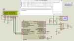
Can anybody help me out with interfacing DS1307 with PIC microcontroller?
I tried it but not getting clock at all on SCl pin.
I have used 1.2k pull ups on both SCL and SDA.
I am using XC8 compiler and MSSP module to achieve I2C.
I have sent 00 to register 0 that is for seconds as weel as 7th bit for CH.
 

Just if you're not using libraries (manually modifying registers) check for some dumb errors that could have happened.

If using them check if you're initializing the module correctly, you have to configure your MCU as master or slave, set the speed and the CL/DT pins.

I used 1k8 resistors as pull up at low speed (100Kb/s) and it works very well.

Before you finish reading the DS1307 memory, send a 0 to the function (in case of being able to send variables to it). I've been looking for the mistake for days when it was that.

Please give more information so we can make deductions and help you.
 

Hello, thank you for your kind reply.
I have built the ckt on breadboard, i am using internal oscillator block of 18f46k22, FOSC value 29 in configuration bits. Watchdog timer disabled always. When i run the program in hardware, it goes in i2c_read() function but does not come back from it. I varified it by switching on a led before going in that function and clearing it while coming out.

Below is the code.


Code C - [expand]
1
2
3
4
5
6
7
8
9
10
11
12
13
14
15
16
17
18
19
20
21
22
23
24
25
26
27
28
29
30
31
32
33
34
35
36
37
38
39
40
41
42
43
44
45
46
47
48
49
50
51
52
53
54
55
56
57
58
59
60
61
62
63
64
65
66
67
68
69
70
71
72
73
74
75
76
77
78
79
80
81
82
83
84
85
86
87
88
89
90
91
92
93
94
95
96
97
98
99
100
101
102
103
104
105
106
107
108
109
110
111
112
113
114
115
116
117
118
119
120
121
122
123
124
125
126
127
128
129
130
131
132
133
134
135
136
137
138
139
140
141
142
143
144
145
146
147
148
149
150
151
152
153
154
155
156
157
158
159
160
161
162
163
164
165
166
167
168
169
170
171
172
173
174
175
176
177
178
179
180
181
182
183
184
185
186
187
188
189
190
191
192
193
194
195
196
197
198
199
200
201
202
203
204
205
206
207
208
209
210
211
212
213
214
215
216
217
218
219
220
221
222
223
224
225
226
227
228
229
230
231
232
233
234
235
236
237
238
239
240
241
242
243
244
245
246
247
248
249
250
251
252
253
254
255
256
257
258
259
260
261
262
263
264
265
266
267
268
269
270
271
272
273
274
275
276
277
278
279
280
281
282
283
284
285
286
287
288
289
290
291
292
293
294
295
296
297
298
299
300
301
302
303
304
305
306
307
308
309
310
311
312
313
314
315
316
317
318
319
320
321
322
323
324
325
326
327
328
329
330
331
332
333
334
335
336
337
338
339
340
341
342
343
344
345
346
347
348
349
350
351
352
353
354
355
356
357
358
359
360
361
362
363
364
365
366
367
368
369
370
371
372
373
374
375
376
377
378
379
380
381
382
383
384
385
386
387
388
389
390
391
392
393
394
395
396
397
398
399
400
401
402
403
404
405
406
407
408
409
410
411
412
413
414
415
416
417
418
419
420
421
422
423
424
425
426
427
428
429
430
431
432
433
434
435
436
437
438
439
440
441
442
443
444
445
446
447
448
449
450
451
452
453
454
455
456
457
458
459
460
461
462
463
464
465
466
467
468
469
470
471
472
473
474
475
476
477
478
479
480
481
482
483
484
485
486
487
488
489
/*  Name     : RTC1.c
 *  Purpose  : RTC based 3 phase motor on off controller 
 *  Date     : 31/10/2014.
 */
#include <stdio.h>
#include <string.h>
#include <conio.h>
#include <stdlib.h>
#include <xc.h>
#include <htc.h>
#include "p18f46k22.h"
 
// Pin assignments
#define LCDRW           LATDbits.LATD5          /* PORT for RW */
#define TRISD_RW        TRISDbits.TRISD5    /* TRIS for RW */
#define LCDRS           LATDbits.LATD4          /* PORT for RS */
#define TRISD_RS        TRISDbits.TRISD4        /* TRIS for RS */
#define LCDE            LATDbits.LATD6          /* PORT for enable */
#define TRISD_E         TRISDbits.TRISD6   
#define TRISC_GREEN_LED TRISCbits.TRISC0   
#define GREEN_LED       PORTCbits.RC0
#define TRISD_GREEN_LED1 TRISDbits.TRISD0   
#define GREEN_LED1      PORTDbits.RD0
 
#define CH_P1ACVTG    0X59 // AN22 // RD2
#define CH_P2ACVTG    0X5D // AN23 //RD3
#define CH_P3ACVTG    0X41 // AN16 //RC4
 
//************DEF for RTC Program starts//
#define RTC 0XD0  
//************DEF for RTC Program ends//
// fn delarations
void nop(void);
void delay(unsigned char);
void fetchstring(const char *);
void writestring (unsigned char); 
void commandLCD(char);
void welcomemsg(void);
void ownermsg(void);
void initialise(void);
void init_lcd(void);
void I2C_INITIALIZE(void);
void I2C_WRITE_WRITE(unsigned char, unsigned char, unsigned char);
unsigned char I2C_READ_DATA(unsigned char, unsigned char);
//int AVG_ADC(int ADCVALUE);
// variable declarations
    unsigned char sec,min,hour,dd,mm,yy;
    int DATA_RTC,hexval,hexval1;
    unsigned char tempregaddr,tempcmd;
 
    int MUKESH1,MUKESH2,MUKESH3,MUKESH11,MUKESH22,MUKESH33;//td
    char temp,temp1,temp2,temp3,Byte,two_d_flag = 0,n=0;
    char lsb1,msb1,mid1,lsb2,msb2,mid2,lsb3,msb3,mid3;
    char TEMP_CHSEL;
    char ACAVGBIT;
    int PASS_ADCVALUE,ADCVALUE,ADCVALUE1,ADCVALUE2,ADCVALUE3,ADCVALUE4,lsb,msb,mid;
    int quotient,reminder;
    int lsbbyte_hexno;
    int DIVI,QUOT,ACVG,ACVG1,ACVGTEMP,NEWACVGTEMP;
    int temp_adc1,temp_adc2,temp_adc3=0;
 
    int ADRES10BIT,ADRES10BIT1,ADRES10BIT2;
    int SHIFTED_L8_ADRESH;
 
    int AVERAGE1=0,AVERAGE2=0,AVERAGE3=0,AVERAGE4=0,AVERAGE5=0,AVERAGE6=0,ADC_TEMP=0;
    
    unsigned char s1[] =          "TANKERPACIFIC";
    unsigned char s2[] =          "   ";
    unsigned char s3[]=           "   ";  
 
    unsigned char owner[]=        "RTC BASED MOTOR ";
    unsigned char alliswell[]=    "   CONTROLLER   ";  
    unsigned char agrileaders[]=  " CUM 24 HR CLK  ";  
    unsigned char technicalfarms[]="PROJECT FOR  ";
    unsigned char MOBILE[]="MOB : ";  
 
    unsigned char allphok[]=      "ALL PHASES R OK ";  
    unsigned char enjoy[]=        "     ENJOY!!!   ";  
 
    unsigned char phase1vtg[]=    "PHASE 1 =    VAC";
    unsigned char phase2vtg[]=    "PHASE 2 =    VAC";
    unsigned char phase3vtg[]=    "PHASE 3 =    VAC";
 
    unsigned char freq[]=         "FREQUENCY =   Hz";
 
    unsigned char p1p2p3vtg[]=    "P1   P2   P3 VAC";
 
    unsigned char phase1error[]=  "FAULT P1 LOW VTG";  
    unsigned char phase2error[]=  "FAULT P2 LOW VTG";  
    unsigned char phase3error[]=  "FAULT P3 LOW VTG";
 
    unsigned char ph1highfault[]= "FAULT P1 HI VTG ";  
    unsigned char ph2highfault[]= "FAULT P2 HI VTG ";  
    unsigned char ph3highfault[]= "FAULT P3 HI VTG ";  
 
    unsigned char p1p2p3vtgON[]=  "P1   P2   P3  ON";  
    unsigned char p1p2p3vtgOFF[]= "P1   P2   P3 0FF";  
    unsigned char VAC[]=          "V";  
 
// fn definations
void initialise(void)
{
       TRISB = 0X00;          //LCD DATA PORT : PORT B AS AN O/P PORT
       TRISD_RW = 0;
       TRISD_RS = 0;
       TRISD_E = 0; 
       TRISC_GREEN_LED = 0;
       TRISD_GREEN_LED1 = 0;
       GREEN_LED = 0;
       GREEN_LED1 = 0;
       PORTB = 0X00;
       OSCTUNE = 0X80;
       OSCCON = 0X76;       // 66:- 8 Mhz,76:- 16Mhz INTERNAL OSCILLATOR : CONFIG WORD VALUE - 29
       OSCCON2 = 0X00;
       INTCONbits.PEIE = 0;
       INTCONbits.GIE =  0;
}
/************delay***************/
void nop(void)
{
    CLRWDT();
    unsigned int i=0;
    for(;i<100;i++);
}   
 
void delay(unsigned char i)
{
    for(;i!=0;i--)
    {
      nop();
      nop();
      nop();
    }
}
void init_lcd(void)
{
    CLRWDT();
     unsigned char a[5]={0x38,0x0c,0x01,0x06,0x80};//8 bit, sh cur,no bl, cur off,scr on, first line
         unsigned char i;
      for(i=0;i<5;i++)
        {
           commandLCD(a[i]);
           delay(40);
        }
}
void i2c_initialize()
{
TRISCbits.TRISC3=1;   //SCL
TRISCbits.TRISC4=1;   //SDA
SSP1ADD=0x27;//13;//27; //100Khz @ 16MHz,Clock=Fosc/(4x(SSPADD+1)
SSP1STAT=0x80; //Disable Slew Rate
SSP1CON1=0x28; //Enable Synchronous Serial Port 
              //I2C Master mode, clock = FOSC / (4 * (SSPADD+1))//21/10/14 by mukesh
SSP1CON2=0X00;
}
void commandLCD(char temp2)
{ 
    CLRWDT();
    TRISD_RW = 0;
    TRISD_RS = 0;
    TRISD_E = 0; 
    PORTB = temp2; 
    LCDRS = 0;        // cmd mode
    LCDRW = 0;        // LCDRW = 0 : write to LCD
    LCDE = 1;
    delay(40);
    LCDE = 0;
}
void fetchstring(const char *s)
{
     while(*s)
       writestring(*s++);
}
void writestring(unsigned char data)  
{   
       CLRWDT();
       PORTB = data;
       LCDRS = 1;        // char mode
       LCDRW = 0;        // LCDRW = 0 : write to LCD
       LCDE = 1;
       delay(40);
       LCDE = 0;    
}
void welcomemsg(void)
{
    CLRWDT();
    commandLCD(0x01);   //clear display
    delay(40);          
    commandLCD(0x80);   //1st line 
    delay(40);       
    fetchstring(&s1[0]);
    delay(500);
    commandLCD(0xc0);
    delay(40);
    fetchstring(&s2[0]);
    delay(500);
}
void ownermsg(void)
{
        CLRWDT();
        commandLCD(0x01);
           delay(40);
        commandLCD(0x80);
           delay(40);
           fetchstring(&owner[0]);
           delay(500);
        commandLCD(0xc0);
           delay(40);
           fetchstring(&alliswell[0]);
           delay(500);
           delay(500);
           delay(500);
        commandLCD(0xc0);
           delay(40);
           fetchstring(&agrileaders[0]);
           delay(500);
           delay(500);
           delay(500);
        commandLCD(0xc0);
           delay(40);
           fetchstring(&technicalfarms[0]);
           delay(500);
           delay(500);
           delay(500);
        commandLCD(0xc0);
           delay(40);
           fetchstring(&MOBILE[0]);
           delay(500);
           delay(500);
           delay(500);
}
void i2c_start(void)
{
    SSP1CON2bits.SEN = 1;//send a start signal.
    while(SSP1CON2bits.SEN == 1);//wait to finish
//    while((SSP1CON2 & 0x1F) | (SSP1STATbits.R_W));//wait until idle 
    while(SSP1CON2bits.RSEN == 1);//wait untill idle
    while(SSP1CON2bits.PEN == 1);//wait untill idle
    while(SSP1CON2bits.RCEN == 1);//wait untill idle
    while(SSP1CON2bits.ACKEN == 1);//wait untill idle
    while(SSP1STATbits.R_W == 1);//wait untill idle
}
void i2c_address(unsigned char slaveaddr)
{
    SSP1BUF = slaveaddr;
    while(SSP1STATbits.BF==1); //wait until all bits are transmitted
//    while((SSP1CON2 & 0x1F)|(SSP1STATbits.R_W));//wait until idle
    while(SSP1CON2bits.RSEN == 1);//wait untill idle
    while(SSP1CON2bits.PEN == 1);//wait untill idle
    while(SSP1CON2bits.RCEN == 1);//wait untill idle
    while(SSP1CON2bits.ACKEN == 1);//wait untill idle
    while(SSP1STATbits.R_W == 1);//wait untill idle
    while(SSP1CON2bits.ACKSTAT==1);
}
void i2c_write(unsigned char cmd)
{
    tempcmd = cmd; 
    SSP1BUF = tempcmd;
    while(SSP1STATbits.BF==1); //wait until all bits are transmitted
//    while((SSP1CON2 & 0x1F)|(SSP1STATbits.R_W));//wait until idle
    while(SSP1CON2bits.RSEN == 1);//wait untill idle
    while(SSP1CON2bits.PEN == 1);//wait untill idle
    while(SSP1CON2bits.RCEN == 1);//wait untill idle
    while(SSP1CON2bits.ACKEN == 1);//wait untill idle
    while(SSP1STATbits.R_W == 1);//wait untill idle
    while(SSP1CON2bits.ACKSTAT==1);
}
void i2c_stop()
{
    SSP1CON2bits.PEN=1; //send STOP signal
    while(SSP1CON2bits.PEN==1);//wait to finish
//    while ((SSP1CON2 & 0x1F)|(SSP1STATbits.R_W));//wait until idle 
    while(SSP1CON2bits.RSEN == 1);//wait untill idle
    while(SSP1CON2bits.PEN == 1);//wait untill idle
    while(SSP1CON2bits.RCEN == 1);//wait untill idle
    while(SSP1CON2bits.ACKEN == 1);//wait untill idle
    while(SSP1STATbits.R_W == 1);//wait untill idle
}
void i2c_restart()
{
    SSP1CON2bits.RSEN=1; //send RESTART signal
    while(SSP1CON2bits.RSEN==1);//wait to finish
//    while ((SSP1CON2 & 0x1F)|(SSP1STATbits.R_W));//wait until idle 
    while(SSP1CON2bits.PEN == 1);//wait untill idle
    while(SSP1CON2bits.RCEN == 1);//wait untill idle
    while(SSP1CON2bits.ACKEN == 1);//wait untill idle
    while(SSP1STATbits.R_W == 1);//wait untill idle
}
void i2c_read(unsigned char regaddr)
{
    tempregaddr = regaddr;
    i2c_start();
    i2c_address(0xD0);
    i2c_write(tempregaddr);
    i2c_restart();
//led bcomes 0 here if made
    i2c_address(0xD1);
//led bcomes 0 here if made
    SSP1CON2bits.RCEN=1; //Enables Receive mode for I2C
    while(SSP1CON2bits.RCEN == 1);//wait untill idle ////
    while(SSP1STATbits.BF==0); //wait until all bits are received
    DATA_RTC=SSP1BUF;//copy received data//21/10/14 by mukesh
////    while(SSP1STATbits.BF==0); //wait until all bits are received
////    DATA_RTC=SSP1BUF;//copy received data//21/10/14 by mukesh
/////           GREEN_LED1 = 0;
//    while ((SSP1CON2 & 0x1F)|(SSP1STATbits.R_W));//wait until idle 
////    while(SSP1CON2bits.RSEN == 1);//wait untill idle
////    while(SSP1CON2bits.PEN == 1);//wait untill idle
////    while(SSP1CON2bits.RCEN == 1);//wait untill idle
////    while(SSP1CON2bits.ACKEN == 1);//wait untill idle
////    while(SSP1STATbits.R_W == 1);//wait untill idle
    SSP1CON2bits.ACKDT=1; //Acknowledge Data bit=1 ie NACK
    SSP1CON2bits.ACKEN=1;//start NACK signal
/////    while(SSP1CON2bits.ACKEN==1);//wait to finish
//    while ((SSP1CON2 & 0x1F)|(SSP1STATbits.R_W));//wait until idle 
////    while(SSP1CON2bits.RSEN == 1);//wait untill idle
////    while(SSP1CON2bits.PEN == 1);//wait untill idle
////    while(SSP1CON2bits.RCEN == 1);//wait untill idle
////    while(SSP1CON2bits.ACKEN == 1);//wait untill idle
////    while(SSP1STATbits.R_W == 1);//wait untill idle
    i2c_stop();
}
 
void bcd_hex(unsigned char RTC_DATA)
{
        hexval=((RTC_DATA>>4) & (0x0F));
        hexval1=(RTC_DATA & 0x0F);
}   
 
/************************* MAIN PROGRAM *****************************/
void main(void)
{
           initialise();
           init_lcd();
           init_lcd();
           init_lcd();
           init_lcd();
           init_lcd();
           welcomemsg();
           delay(500);
           delay(500);
           ownermsg();
           delay(500);
           delay(500);
 
           i2c_initialize();
 
           GREEN_LED1 = 1;
 
           i2c_start();           
           i2c_address(0xD0);
           i2c_write(0x00);//sec reg addr 
           i2c_write(0x00);//sec value
           i2c_stop();
 
           i2c_start();           
           i2c_address(0xD0);
           i2c_write(0x02);//hr reg addr 
           i2c_write(0x04);//hr value
           i2c_stop();
 
           i2c_start();           
           i2c_address(0xD0);
           i2c_write(0x01);//min reg addr 
           i2c_write(0x15);//min value
           i2c_stop();
 
 
           i2c_start();           
           i2c_address(0xD0);
           i2c_write(0x03);//day reg addr 
           i2c_write(0x01);//day value
           i2c_stop();
 
           i2c_start();           
           i2c_address(0xD0);
           i2c_write(0x04);//date reg addr 
           i2c_write(0x16);//date value
           i2c_stop();
 
           i2c_start();           
           i2c_address(0xD0);
           i2c_write(0x05);//mm reg addr 
           i2c_write(0x15);//mm value
           i2c_stop();
 
           i2c_start();           
           i2c_address(0xD0);
           i2c_write(0x06);//yr reg addr 
           i2c_write(0x89);//yr value
           i2c_stop();
 
           i2c_start();           
           i2c_address(0xD0);
           i2c_write(0x07);//cntrl reg addr 
           i2c_write(0x10);////Disable SQW , select oscc freq=32.768Khz
           i2c_stop();
 
           delay(500);
           delay(500);
           delay(500);
           delay(500);
           GREEN_LED1 = 0;
           delay(500);
           delay(500);
           delay(500);
           delay(500);
 
while(1)
{
           init_lcd();
           GREEN_LED1 = 1;
           i2c_read(0x02);
           delay(500);
           delay(500);
           delay(500);
           delay(500);
//           GREEN_LED1 = 0;
 
//           bcd_hex(DATA_RTC);
//           hexval = (hexval+0x30);
//           hexval1 = (hexval1+0x30);
           hexval = ((DATA_RTC/10)+0x30);
           hexval1 = ((DATA_RTC%10)+0x30);
           writestring(hexval);
           writestring(hexval1);
           writestring(':');
           delay(500);
           delay(500);
           delay(500);
           delay(500);
//           GREEN_LED1 = 0;
 
 
           i2c_read(0x01);
//           bcd_hex(DATA_RTC);
//           hexval = (hexval+0x30);
//           hexval1 = (hexval1+0x30);
           hexval = ((DATA_RTC/10)+0x30);
           hexval1 = ((DATA_RTC%10)+0x30);
 
           writestring(hexval);
           writestring(hexval1);
           writestring(':');
 
 
           i2c_read(0x00);
//           bcd_hex(DATA_RTC);
//           hexval = (hexval+0x30);
//           hexval1 = (hexval1+0x30);
           hexval = ((DATA_RTC/10)+0x30);
           hexval1 = ((DATA_RTC%10)+0x30);
 
           writestring(hexval);
           writestring(hexval1);
 
           commandLCD(0xC0); //line 2
           delay(40);
           i2c_read(0x04);
//           bcd_hex(DATA_RTC);
//           hexval = (hexval+0x30);
//           hexval1 = (hexval1+0x30);
           hexval = ((DATA_RTC/10)+0x30);
           hexval1 = ((DATA_RTC%10)+0x30);
           writestring(hexval);
           writestring(hexval1);
           writestring('-');
 
           i2c_read(0x05);
//           bcd_hex(DATA_RTC);
//           hexval = (hexval+0x30);
//           hexval1 = (hexval1+0x30);
           hexval = ((DATA_RTC/10)+0x30);
           hexval1 = ((DATA_RTC%10)+0x30);
           writestring('-');
 
           i2c_read(0x06);
//           bcd_hex(DATA_RTC);
//           hexval = (hexval+0x30);
//           hexval1 = (hexval1+0x30);
           hexval = ((DATA_RTC/10)+0x30);
           hexval1 = ((DATA_RTC%10)+0x30);
           writestring('-');
} 
}
void interrupt ISR(void)
 {
 
 }

 
Last edited by a moderator:

hello


If you are using internal FOSC of 18F46K22,
dont'forget to modify OSCON to get 16MHz , because by default, FOSC=1MHz
i didn't see init of FOSC in your inialise code..

With 1MHz , SSPAD could not be OK
 

Hi, thank you for your reply.
I have made OSCCON to 0x76 in initialisation, which selects internal oscillator frequency to 16 MHz and have varified Tcy to be 4MHz on oscilloscope.
 

I have not made a computer drawing of the circuit.

But i can describe pin connections in the circuit.
Pin no 18(RC3) of 18f46k22 to pin no 6(SCL) of DS1307 with 1.2 KOhm pull up resister connected in between RC3 and +VCC.
Pin no 23(RC4) of 18f46k22 to pin no 5(SDA) of DS1307 with 1.2 KOhm pull up resister connected in between RC4 and+VCC..
32.768 KHz crystal in between pin 1 and 2 of DS1307.
pin no 8 of DS1307 to +VCC ie. +4.89 v ( o/p of 7805 ).
pin no 4 of DS1307 to GND.

Microcontroller pin no 33 to 40 as 2*16 LCD's data port.
Microcontroller pin no 27,28,29 as LCD's RS R/W and E respectively.
Microcontroller pin no 11 and 32 to +VCC.
Microcontroller pin no 12 and 32 to ground.

Microcontrollers ground and DS 1307 ground has been made common.

I am using 16 MHz internal oscillator of 18f46k22.
 

I have used MPLAB and C18 and have done a DS1307 project. I have used C18 built-in I2C library. https://www.edaboard.com/threads/300596/

Zip and post your complete MPLAB project files. I will debug and test it.


Mention which Compiler you are using. In the code I see you have included both xc.h and htc.h. They are for different Compilers. Use 4.7k pullup resistors for I2C lines.

- - - Updated - - -

I found this xc8 code for DS1307.

http://www.studentcompanion.co.za/post/Digital-Clock-using-PIC-Microcontroller-and-the-DS1307-Real-Time-Clock-XC8-Compiler

http://www.studentcompanion.co.za/post/Interfacing-The-DS1307-Real-Time-Clock-With-PIC-Microcontroller-XC8

It will be easy if you use the built-in I2C functions.

- - - Updated - - -

Here are some I2C codes for PIC.

http://www.8051projects.net/i2c-twi-tutorial/pic-i2c-code-example.php

http://saeedsolutions.blogspot.in/2012/12/pic16f877-i2c-code-proteus-simulation.html
 
Last edited:

hello


what about Pin 3 of DS1307
didi you connect a batterie >= 3,00V like CR2032

connect a led between SOUT Pin7 tied to Vcc trought a resitor 1K
led must blink at 1Hz if RTC init is correct
if you don't see the led blinking, no chance to use further the DS1307

Code:
void writeDS1307()
 {
     StartI2C1();	
	WriteI2C1(0xD0);	
	WriteI2C1(0x00);	
	WriteI2C1(sec);// sec
	WriteI2C1(min);//minutes	
	WriteI2C1(hr);// hours	
	WriteI2C1(week_day);//week_day	
	WriteI2C1(day);//date	
    WriteI2C1(mn);//month	
	WriteI2C1(year);//year
	WriteI2C1(0x10);   // REG 7 - [B]Enable squarewave output pin1hz [/B]
	StopI2C1();
}
 

I have modified the code and it works. Test the attached .hex file in hardware and reply. I have tested it in Proteus 8.1 and it works fine.

111287d1415882210-rtc.png


- - - Updated - - -

Disable ADC functions on pins used for I2C and LCD. By default on Power on Reset (POR) pins which have ADC functions are set as analog inputs. Configure ANSELx regsiters. If you are not using Comparators in your project then disable them by configuring (clearing) CM1CON0 and CM2CON0 registers. This is needed if you are using RA0, RA1 and RA2 for ADC (3 Phase reading).
 

Attachments

  • rtc.png
    rtc.png
    74.6 KB · Views: 107
  • DS1307_3PC.production.rar
    3 KB · Views: 51

Thank you very much for your reply.
I have used XC8 compiler.
I will do all the suggested remedies.
 

Thank you very much for your reply.
I have not connected a battery yet.
I will connect the led as suggeted and test it.
 

Hello everyone. Thank you for everybody's help.
Got my problem solved when i built the circuit on PCB.
The same code was working fine which i posted.
 

If someone find this useful, everytime you use a IC READ the datasheet, at least the pin explainations so you can know what is each pin for, how to connect it and if it's necessary to. If you are not using a battery you must ground the IC battery supply pin.
 

Status
Not open for further replies.

Similar threads

Part and Inventory Search

Welcome to EDABoard.com

Sponsor

Back
Top