BKI
Member level 1
I have a negative output voltage (-60V).
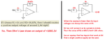
What i plan to do to regulate this voltage is to use a resistor divider at the output to receive a -2,4V signal instead of -60V.
Then, i want to compare this signal with a bandgap reference voltage source.
The problem is now, can i use a comparator to compare? If i use a standard bandgap, it only gives me a positive 2,4V right?
So, how can i sense a negative voltage?