Continue to Site

Welcome to EDAboard.com

Welcome to our site! EDAboard.com is an international Electronics Discussion Forum focused on EDA software, circuits, schematics, books, theory, papers, asic, pld, 8051, DSP, Network, RF, Analog Design, PCB, Service Manuals... and a whole lot more! To participate you need to register. Registration is free. Click here to register now.

problem with APD biasing

Status
Not open for further replies.

israel_Y

Member level 1
Joined
Feb 8, 2010
Messages
34
Helped
0
Reputation
0
Reaction score
0
Trophy points
1,286
Location
The Netherlands
Activity points
1,534
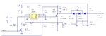
I am trying to bias APD at about 130-140V

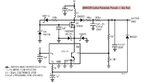
I have found schematics from this forum ( vout = 160V) aswell as from Linear technology application note (http://cds.linear.com/docs/en/application-note/an118fa.pdf) page 7, figure 17, Vout 200.

My problem is that i don't quite understand how the circuits work so i cant adjust them from the nominal output voltage to my needing.

Can someone please explain how they work, or which filed i have to adjust to control the output voltage

Thank you so much in advance.
 

PWM regulator used to drive MOSFET has FB pin to which sample of output voltage through attenuator is connected. For last circuit it is done with 1M and 6.19k resistors and at 200V output voltage FB gets 1.23V. FB is input to error amplifier with reference 1.24V. Take a look at LT1172 datasheet it has internal circuit.
 
Thank you for your reply,

so to get output 140V, if i use 1M and 8.9Kohms, will it give the right result. and do i have to change the other components?
 

In regard your two links resistor selection is OK. Show us your real circuit and up-converter parameters you wanted.
 

The circuit i am planning to adopt is just the one mentioned earlier. One i got from previous edaboard post (https://www.edaboard.com/threads/279515/) and from LT application note. I have attached the images here.
 

Attachments

  • apd_bias_voltage_gen.JPG
    apd_bias_voltage_gen.JPG
    81.5 KB · Views: 59
  • LT app note 118.png
    LT app note 118.png
    55.1 KB · Views: 60

HI,

Maybe you can try DC-DC high voltage convertors from emcohighvoltage. They feature a simple output voltage control using a control voltage input pin. Note that the output of these convertors is load dependent and they need a minimum load to remain within safe operating region. Hope it helps
 

Status
Not open for further replies.

Part and Inventory Search

Welcome to EDABoard.com

Sponsor

Back
Top